0

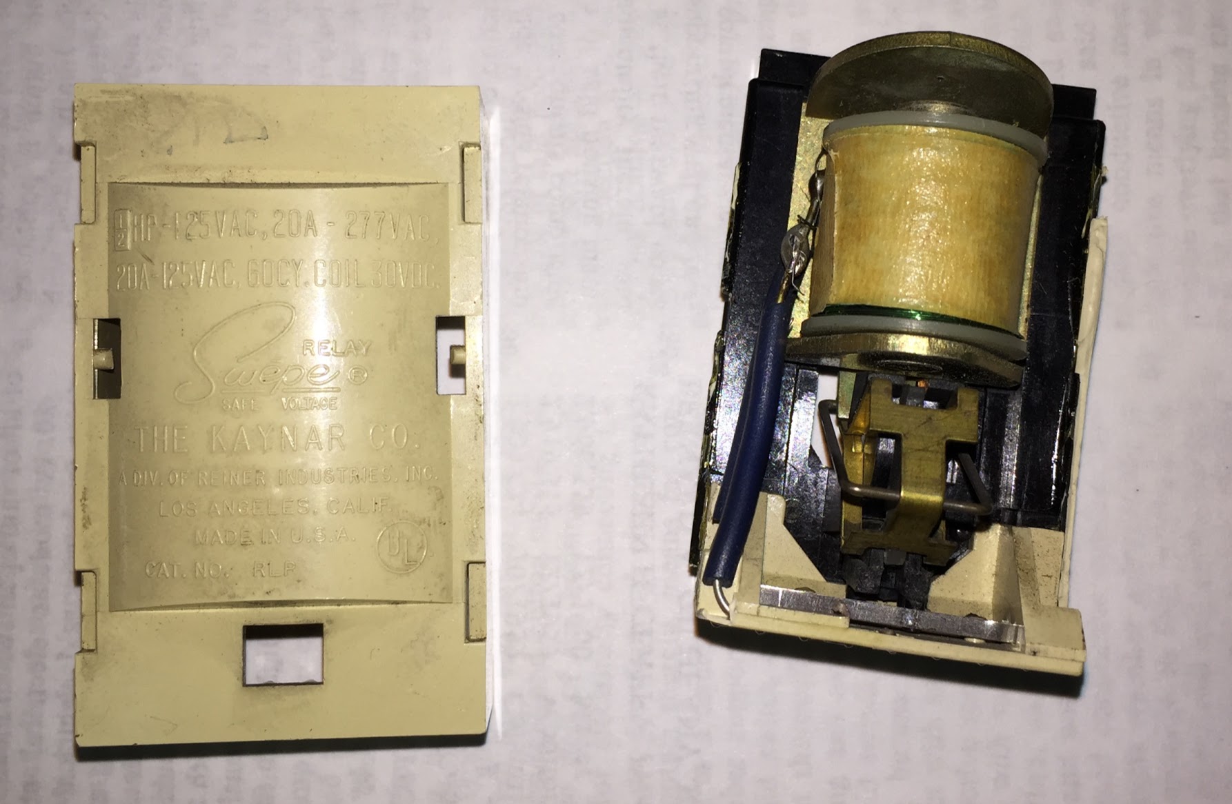
I have old electromechanical relays that were installed in a panel with a transformer as part of a remote controlled lighting circuit. It's a nifty setup except the relays are no longer manufactured. Here is a patent that describes the relay. The relay itself is marked:

1/2 HP - 125VAC, 20A-277 VAC

20A-125VAC, 60 CY., COIL 30VDC

And it accepts four pairs of DC inputs that seem to have 200-400 mV when a particular light is ON and 30V when the light is OFF.

What does 1/2 HP mean here? Why are there two different ratings for VAC (i.e., 20A-277 and 20A-125VAC)?

My goal here is to find something I could use to replace these components without having to redo the entire panel. enter image description here
17
  • Do you mean that the single relay accepts four inputs? Commented Mar 18, 2017 at 17:51
  • 1
    Is the switch that controls the relay momentary or maintained contact? If momentary, you can probably use a GE model RR7 relay (still made and sold) as a replacement. If the switch contact is not momentary a Remcon relay product is likely what you will need. Remcon is owned by Amprobe now.
    – Tyson
    Commented Mar 18, 2017 at 18:03
  • It has eight DC terminals (four +/- pairs) Commented Mar 18, 2017 at 18:05
  • @Tyson -- actually, I was going to suggest something from the Functional Devices RIB line as a replacement...but with all the weirdness on this part, probably not. Commented Mar 18, 2017 at 18:05
  • Yea the 8 DC terminals makes no sense. @ThreePhaseEel
    – Tyson
    Commented Mar 18, 2017 at 18:06

2 Answers 2

1
  • 1/2 hp is a motor rating. Motors have a whole bunch of inductive kick, so controlling relays must be de-rated.
  • 20A is the rating at 277V. Interesting thing, 277V was commonly used in industrial lighting, where they were interested in a high ratio of lumens to copper (40kw on twelve 12AWG wires); so 277V almost implied HID lighting with magnetic ballasts (sodium, metal halide, etc.) This is called a "ballast load" because they too have an inductive kick, though not like a motor. This seems to imply a 20A rating for ballast load.
  • 20A is the rating at 120V. 120V lighting tended to be incandescents, i.e. a simple resistive load with no kick. Incandescents do have an inrush current which is considerable, so contacts need to be a little tougher than a pure resistive load. By the way, electronic ballasts and LEDs also have inrush current from the capacitors/inductors charging up.

The 30V DC is approximately what you get when you take a common 24VAC thermostat or doorbell transformer and rectify it to DC. Very appropriate for a 1960s system.

4
  • It looks like this solid state device has identical ratings except for it is rated to handle only 10A with an incandescent load. Would it be safe for me to try it? Commented Mar 19, 2017 at 13:32
  • @MichaelF.Martin I think you'll find that your linked relay is not directly compatible with your momentary contact switching.
    – Tyson
    Commented Mar 19, 2017 at 15:26
  • @MichaelF.Martin Yes, Tyson is right. The existing relay is a latching relay, i.e. you energize one coil momentarily to snap it on... and energize the other coil momentarily to snap it off. Once coil power is removed, it stays where it was last set (on or off). RiBs are great relays, and that one isn't a latching relay, but they make others that are. Also they are mechanical relays, which you need for latching. Commented Mar 19, 2017 at 15:36
  • Good heads up. Having reviewed the patent description of the plug-in relays, I'm now thinking they might not be designed for momentary contact. The patent specification together with the fact that the DC Voltage stays high at 30V the entire time the switch is off suggests to me that they are not momentary contact. But I will fiddle around a little more and see. Commented Mar 20, 2017 at 1:30
0

To Summarize comments and provide an answer to your issue.

The GE RR7 relay is a suitable replacement in your system. Electrically it has the characteristics required for your needs and is manufactured for use in a similar Low Voltage switching system.

You will have to adapt mounting to work for your panel. The line side relay is two terminals and wires just like a single pole switch. You will need to figure out which wire is which on the low voltage side of your house wiring. There is a diagram on the relay or the printed sheet that shows which wire color of the low voltage is which. Low Voltage wires are Momentary-On, Common, and Momentary-Off.

You mentioned 4 conductors to each switch, if your switches have a pilot light (on/off Indicator) then you need GE RR9 relay instead of a RR7.

RR7P is the SAME thing as an RR7 except that it has a plug connector on the low voltage wires that fits GE's cabinet. Cut the plug off and you have an RR7.

Related reading in this similar but different question.

3
  • I wish I could credit both of these answers. This is very helpful, but having reviewed them I believe it is more in keeping with the guidelines for me to give Harper the credit here since he literally answered the questions I asked. Commented Mar 20, 2017 at 1:27
  • @MichaelF.Martin I saw the real question as "My goal here is to find something I could use to replace these components without having to redo the entire panel." Also, an upvote awards partial points.
    – Tyson
    Commented Mar 20, 2017 at 1:34
  • Reading over the patent again, I believe this is actually not a momentary contact switch. Each plus line of low voltage is useful (and only useful) for closing the relay. Each minus line of low voltage is useful (and only useful) for opening the relay. Momentary contacts are described as an alternative to this arrangement in the patent specification. Commented Jun 23, 2018 at 16:39

Your Answer

By clicking “Post Your Answer”, you agree to our terms of service and acknowledge you have read our privacy policy.

Not the answer you're looking for? Browse other questions tagged or ask your own question.