2

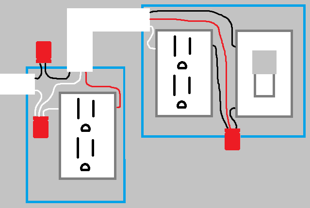
I'm trying to connect a new switch and two new outlets (from switch) to an existing electric line. This new switch should turn the two new outlets on and off.

However, I'd like to connect it as follows:

  • Existing power is closest to new outlet #1.
  • New light switch and new outlet #2 are on the other side of the room and located next to each other.

Are there any wiring diagrams to explain how to connect this? I think I can do this with my 14-2 wire but I'm not positive.

EDIT: Does this diagram look correct? Switch Diagram

3
  • 1
    Do you want "-->sw. outlet-->switch-->sw. outlet" or "-->sw. outlet-->sw. outlet-->switch"? Commented May 27, 2016 at 1:27
  • Either is fine, but I'd prefer the later. (power -> sw. outlet -> sw. outlet -> switch) Thanks so much!
    – SofaKng
    Commented May 27, 2016 at 1:36
  • Since this is controlling a switched receptacle, the neutral does not need to be present at the switch as per 404.2(C)(7) -- just remember to retag the white wire in the switch loop as a hot! Commented May 27, 2016 at 22:12

3 Answers 3

2

If the power enters at the first receptacle outlet, then you can wire it as follows:

At the receptacle outlet box

  • 14/2 feed into the receptacle outlet box.
  • 14/3 between the receptacle outlet box and the other outlet box.
  • Connect white wire from 14/2 feed to the silver screw on the receptacle, and the white wire from the 14/3 cable going to the other box.
  • Connect the black wire from the 14/2 feed, to the black wire of the 14/3 cable.
  • Connect the red wire from the 14/3 cable, to the brass screw on the receptacle.
  • Connect all grounding conductors to box and device.

At the other outlet box

  • Connect the white wire from the 14/3 cable to the silver screw on the receptacle.
  • Connect the black wire from the 14/3 cable to one of the switch terminals.
  • Connect the red wire from the 14/3 cable to the brass screw on the receptacle, and the other switch terminal.
  • Connect all grounding conductors to box and device.

Switch controlled receptacles
Grounding conductors not shown for simplicity

1
  • I've edited the original post to include a diagram. Does it look correct?
    – SofaKng
    Commented May 27, 2016 at 13:47
1

Just use outlet box #1 as both a junction box & outlet box. Having enough room in the box shouldn't be a problem, but you can always get a deeper box if desired. Wire nut the supply to another 14/2 running to the switch. Then, you'll run a new 14/2 back to outlet box #1 to power the outlet. Finally, simply run another 14/2 from outlet #1 to outlet #2.

Follow manufacturer's instructions, if provided. But, Black Wire to Brass or Black screw. White Wire to Silver screw (may or may not apply to the switch). Ground or Bare wire to Green Screw. Just Whites (if applicable) & Grounds or Bares at switch would be Pig-tailed to the Switch...pig-tail is a 3rd wire chunk of 6" or 8" that is wire-nutted to the 14/2 wires. This pigtail is the only thing that gets attached to the Switch's Silver (if applicable) & Green screws.

6
  • Thanks very much for the reply but the problem is that I'm unsure how to wire it. (i.e. hot/neutral wires)
    – SofaKng
    Commented May 27, 2016 at 1:52
  • Sorry, I'll add-on.
    – Iggy
    Commented May 27, 2016 at 1:55
  • Thanks again so much! Are there any diagrams available by any chance? :)
    – SofaKng
    Commented May 27, 2016 at 2:14
  • There are different ways to handle your situation & I couldn't find, my easiest or most straightforward, in a top of the page full diagram at this moment. But, just tour Google Images for a visual that works for you.."switched outlets diagram". I prefer my method because the outlets are separated from any supply power & therefore future confusion or mistakes in replacing an old outlet.
    – Iggy
    Commented May 27, 2016 at 2:26
  • Why would the white (neutral) be attached to the switch? If you're switching neutral, you're doing it wrong.
    – Tester101
    Commented May 27, 2016 at 3:40
1

[much better answer by Tester101. Will delete this answer tomorrow once OP has a chance to see redirection]

5
  • I've edited the original post to include a diagram. Does it look correct?
    – SofaKng
    Commented May 27, 2016 at 13:47
  • 1
    Your diagram is almost correct. But you need a neutral going to the switch, even though you are not using it now. So you need three wire between the first outlet and the switch W for neutral, B for hot and R for switched hot. Also, the first outlet box can serve as the junction box as well.
    – bib
    Commented May 27, 2016 at 14:37
  • 1
    @bib -- he actually does not -- 404.2(C)(7) exempts switches controlling receptacles. Commented May 27, 2016 at 22:13
  • @ThreePhaseEel I learn something from my friends here almost every day! I will amend. (He still needs 14/3 between outlet 1 and two unless he want a full direct run to the switch first.)
    – bib
    Commented May 27, 2016 at 23:16
  • See redirection to Tester101's answer.
    – bib
    Commented May 27, 2016 at 23:26

Your Answer

By clicking “Post Your Answer”, you agree to our terms of service and acknowledge you have read our privacy policy.

Not the answer you're looking for? Browse other questions tagged or ask your own question.