2

My doorbell recently stopped working, after a decorator painted my hallway.

It is a wired system with a bell transformer beside the consumer unit. There are 2 wired bell units inside the house – one downstairs and one upstairs.

I'm handy with a multimeter but I do not have access to the junction box that connects all the wires together, without ripping all the paper off the wall and needing redecoration. There is only one pair of wires leaving the transformer, and only one pair leading to the switch and each of the two bells – so I know there must be some kind of junction somewhere. It would help if I knew exactly where! These wires are all of different ages and appearances, as they were commissioned at different times, so I know I can't be mistaken in this.

The bells are wired in parallel.

The transformer is working and is generating approximately 14V AC.

Measuring the voltage across the switch, I see the same. Pressing the button, the voltage drop across the switch goes to 0V. However, neither of the bells ring. The switch is of the kind that lights up when it is not being pressed, but it is no longer illuminating, even though there is 14V AC present.

I did manage to persuade someone to press the switch while measuring the voltage across one of the bells. It stayed at 0V.

All the connections seem to be sound.

What should my next steps be? Are there any further practical diagnostic steps I can make, or do I now need to start making holes in stuff looking for the junction box?

Once I find the box I know how to check the resistance of each leg looking for the break. But can I do anything useful without finding it? I have access to a mains cable detector, but does that work with the lower voltages a doorbell works at?

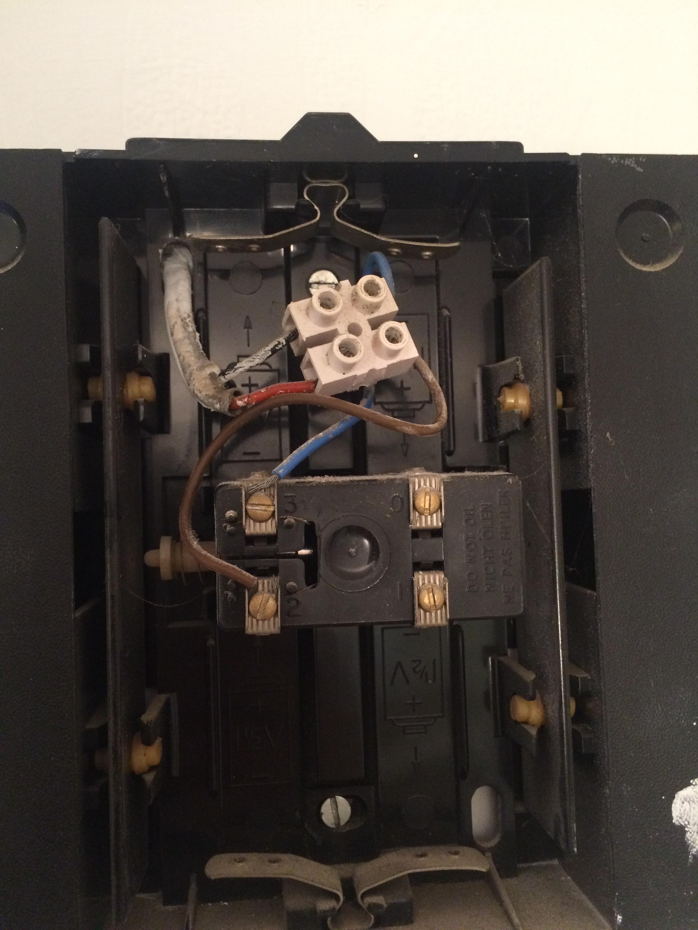
Here are some pictures of the various parts of the system:

Bell transformer

Bell switch with light

Downstairs bell

Upstairs bell

Update

I first tested the current drawn by shorting out the switch contacts, using a multimeter. I got 0mA.

Then I found a long length of speaker wire. With the help of a chock block, I traced the continuity between the various parts of my circuit.

I have a good connection from one side of my transformer to one side of the switch.

I have a good connection from the other side of the transformer to one side of both bells, which means they are definitely wired in parallel.

The other side of the bell units are connected to each other as well, confirming they are in parallel.

Unfortunately, the other side of the switch is open circuit to the other side of the bell units.

Sadly, I think this means I need to run a new wire.

Update: Fixed!

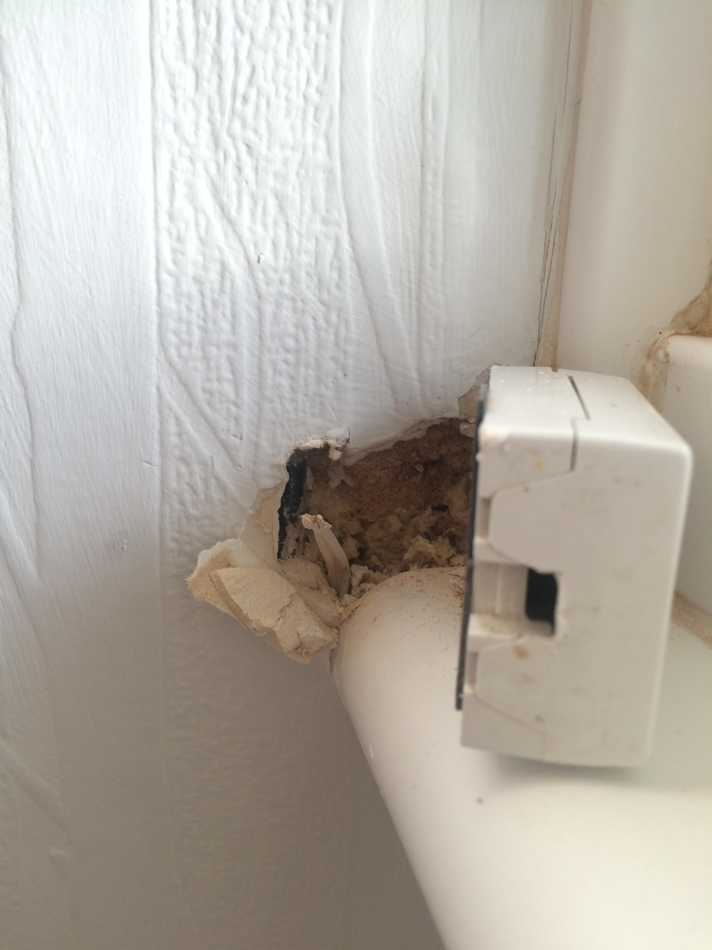
Having used a sufficiently long piece of speaker cable, and tracing the open circuit connection to the cable run between the switch and the junction box (whose precise location is still not known) suspicion fell on a newly drilled hole, intended to fix the telephone cable junction box more firmly to the wall.

After digging out the wall behind the junction box sufficiently, we could see the new hole had indeed hit the bell cable and light pressure was sufficient to completely separate the wires - though at first, only one part was visible.

A suspicious wire which doesn't go anywhere

Further digging exposed the other part of the wire, and we were able to reconnect the ends with a chock block.

Re-united with its partner - and a rawl plug whose need was the cause of the whole sorry affair

Putting everything back together I now have two working bells. And the hole was small enough that it could be filled and completely hidden by the junction box for the telephone. Result!

Thanks to everyone for your excellent advice.

3
  • Can you measure the current across the switch when you close it? Can you run (external) wires from each side of the transformer to near one of the bells and see what the mutual voltages are? Commented Jan 15, 2016 at 14:35
  • I can try measuring the current at the switch when I close the circuit there, sure. I was trying to avoid finding 15 meters of cable if there were other steps I could try first. Commented Jan 15, 2016 at 14:48
  • You should post the eventual fix as "an answer" so it's clear to followers what happened here... :)
    – rogerdpack
    Commented Oct 13, 2018 at 14:30

2 Answers 2

2

"I can think of all sorts of tests I could run if the ends of the wires were close enough together that I could reach both ends with the multimeter at the same time."

Could you not get a long length of wire (or even hack an extension reel) to clamp to one end of a wire to bring it near to one you want to test?

1
  • I found some old speaker cable that was long enough to reach between the various key points. This has helped. Thank you. Commented Jan 15, 2016 at 17:24
3

If it stopped after painting, then I would guess that it has nothing to do with what's behind the wall. (Unless they were able to get behind the walls themselves) Could be just bad luck, but I'd suggest checking the wiring connections on the bells. Take them off and reconnect them if needed.

Could your system be connected together at the bells?

Bell system


After the comments below, I've (terribly) tried to draw up what it sounds like it looks like. Wiring diagran

My best guess is that there used to be an old transformer that was used for the old bell and button. The contractor that added the new transformer would have removed the old one and used it's box, or wherever it was located, as the junction location to reconnect everything.. Does this sound reasonable? Since you have power to the light switch, but neither bell works, the issue must be between the button and the junction box or between the junction box and your new transformer. It could be a wire that's come loose in the box or something that's interrupted one of those two wires.

You might call the old contractor and ask about this possibility? If they did something like this, they should know where the box was.

11
  • It is not connected at the bells. There are 3 different types of wire in use, and each end point only has one type of wire approaching it. The decoration was more complicated than just painting, and did include some screwing of fixtures to walls. It is possible, even if unlikely, that one of the screws has broken a wire. Commented Jan 15, 2016 at 14:07
  • The button and the original bell have a two-core wires running to them. The electrician who replaced our consumer unit last year fitted an extension bell upstairs and a new transformer downstairs beside the consumer unit. The low voltage wiring he fitted at the time actually uses telephone cable (4-core twisted pair). Each terminal has both wires from one of the pairs connected to it – it seems to have been done just to increase the current carrying capacity. Commented Jan 15, 2016 at 14:16
  • The low voltage wire at the transformer heads straight up towards the ceiling and behind a stud partition so I can't see where it goes then. The wire to the switch runs into the plastic windowsill under the window beside the front door, which has since been filled with filler so I can't see where it goes then. The wire to the original bell has been in the house for as long as I have lived there, and could go anywhere. The run to the upstairs bell runs all over the place; it was fitted at the same time the garage conversion was being done, so he had access to bare bricks… Commented Jan 15, 2016 at 14:21
  • I can think of all sorts of tests I could run if the ends of the wires were close enough together that I could reach both ends with the multimeter at the same time. Commented Jan 15, 2016 at 14:34
  • There is an mcb in the new consumer unit with a short tail of mains wire running to the input to the transformer. The transformer itself is screwed to the same board that the consumer unit and the electricity meter are mounted on. The output runs upwards towards the ceiling, but quickly disappears behind a false wall, which was added to cover up the extra layer of thermal insulation that was needed when they did the garage conversion. The voltage across the old wires is now 0V AC whether or not the switch is pressed. Commented Jan 15, 2016 at 14:40

Your Answer

By clicking “Post Your Answer”, you agree to our terms of service and acknowledge you have read our privacy policy.

Not the answer you're looking for? Browse other questions tagged or ask your own question.