1

We are looking to expand our kitchen into a space that I figured was a load bearing wall.

Details:

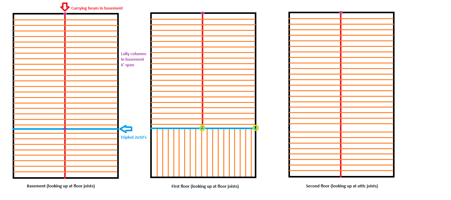
1st floor, the truss joists all go from front to back of our home. I noticed the section where there were 2x10s tripled up (which happens to be on the portion of wall that I want to remove).

2nd floor, the truss joists run perpendicular to the rest of the house. I am assuming they built it this way to allow there to be a wide open 12x26 room. Using an interior wall to support the other side of the 2nd floor joists.

Attic, stick built wide open attic. Wall in question runs parallel with the roof trusses, so no roof load from what I can see.

My question, it seems that this load bearing wall supported the weight of 2 things. The one side of the second floor trusses and the wall on the second floor above it. It doesn't seem to be supporting anything in the attic.

The perpendicular trusses on the second floor are side hung off of the truss going from front to back, then that truss is supported by that wall that I want to remove.

My hopes are to span the 13' with supports located (circled in green).

My theory is that they are currently depending on three 2x10s in the basement to hold all of the weight that I mentioned above, along with the weight of the wall that I am wanting to remove. Hypothetically, three 2x10s sistered as my beam would provide the same, if not more than needed capacity for the wall that I want to remove.

I've been told to take this to a lumberyard and they can calc it out, but I'm open to others ideas. I don't want a visible beam, so I would just cut back the floor joist to slip in a couple 1.75x9.5" LVLs on each side of the current joist that is currently carrying the perpendicular joists.

Sorry if this is confusing, I honestly have no idea how to type this out for anyone to understand.

Thanksenter image description here

5
  • 3
    Try your lumberyard. They may have adequate "packaged engineering software" to think they can advise you, or they may send to off to consult an actual Licensed Professional Engineer for your specific case. You'll be betting your house on the ruesults, so be sure.
    – Ecnerwal
    Commented Feb 20 at 20:33
  • 1
    In the future, drawings of architecture are from top down ("plan view"). This "looking up" business is really discombobulating.
    – isherwood
    Commented Feb 20 at 20:40
  • Does the existing 3-2x10 have a break at the interior column? If not, then the rotation restraint provided by the balanced loads on either side of the column increases the strength of the beam. Without such rotational restraint for your new header, it would not have the same strength as the lower beam.
    – popham
    Commented Feb 21 at 8:02
  • That existing joist that the odd joists tie into (presumably it sits on top of your load bearing wall) is probably acting as a rim board to restrain the rotation of the odd joist ends. If the odd joists are attached merely by face nailing, then you'll need joist hangers. Additionally, attaching the adjacent pieces sufficiently is important so that all of the pieces work together to support the odd joists. Nailing schedule for such things is found in the table under IRC R602.3.
    – popham
    Commented Feb 21 at 8:08
  • What is the span length for the odd joists? There's a table under IRC R602.7, Table R602.7(2), that will size your header and give you a jack stud count. You would use the odd joist span length as "building width" in that table. (An obsessive compulsive person would increase the span length by half the distance from the 3-2x10 to its adjacent, parallel joist to account for the whole tributary area.) If sleeping rooms are above the header, then the table will size the header for an extra 33%
    – popham
    Commented Feb 21 at 8:15

2 Answers 2

1

We're speaking generally here as I can't see the details of the framing. However, I see no real concerns with your plan, assuming...

  • The interior post is directly bearing on the primary beam in the basement, with full blocking. You must not depend on subfloor spans. The tripled joists you mentioned may handle this already.

  • The basement beam is up to the point load task. It probably is, especially if there's a supporting post there or nearby.

  • The exterior post is installed within the exterior wall and adequate for the load. This may require a tripled stud directly under it.

  • The exterior post is similarly blocked to the foundation wall below, which must directly carry it.

  • The new beam is sized by an engineer (or reasonable facsimile) for the second floor load. All advice garnered therein will supersede anything we've said here.

1
  • 2
    The engineer will be able to evaluate all the earlier points too, and possibly suggests solutions for them. (In my case, sistering one joist with iron C-beam to transfer the added load appropriately.)
    – keshlam
    Commented Feb 20 at 21:07
0

Use Table R602.7(2) under IRC R602.7 to size the header for #2 grade sawn lumber from a local lumber supplier. Using the table is a little tricky because its entries are predicated on "building width."

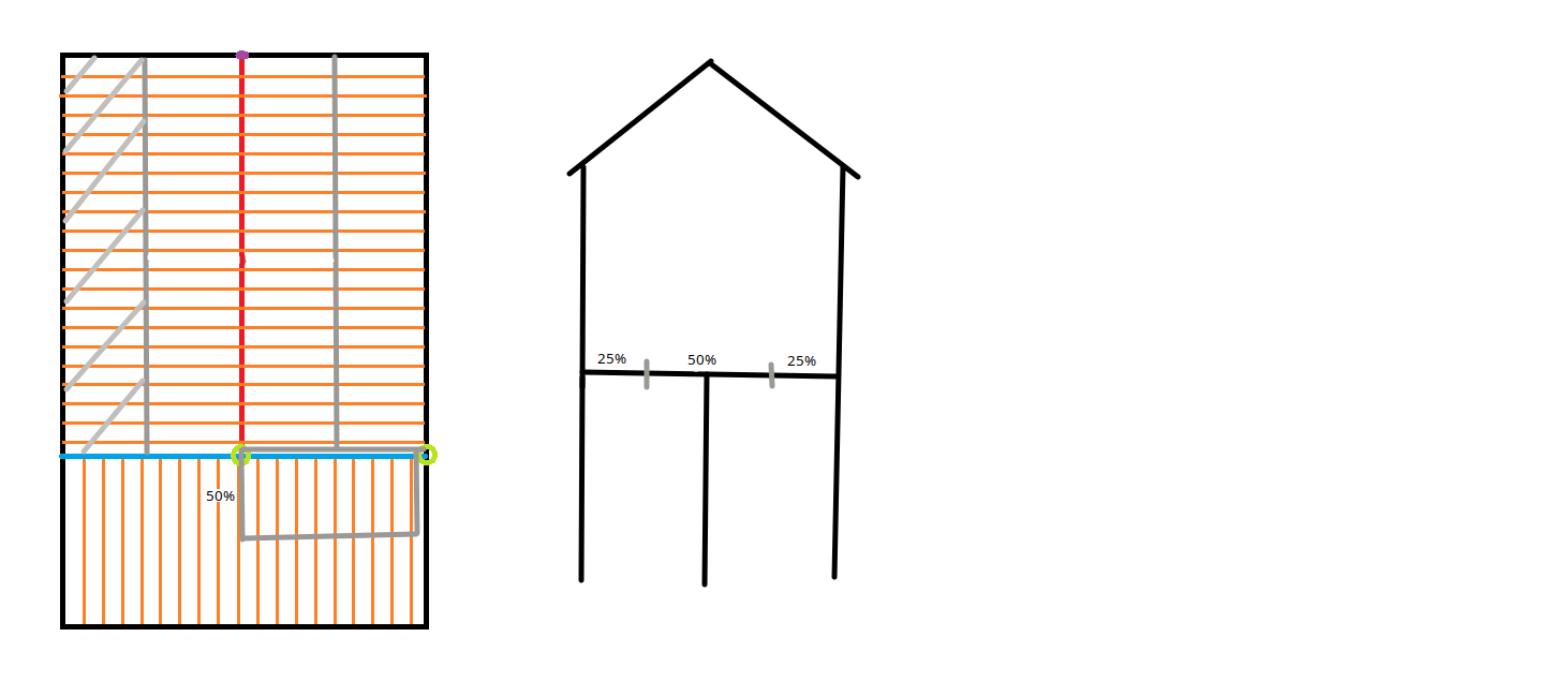
You can use the joist span lengths as the "building width" in your case. To understand why, look at the modifications that I have made to your drawing:

Layout tributary widths

I've marked some tributary area boundaries on the drawing. The left exterior wall, for instance, gets the psf loading from the cross-hatched area adjacent to it. For your beam, I've marked the boundary of its tributary area. The tributary area has 50% of the joist span length as its width. The load on your beam from dead and live load would be w = (10 psf + 40 psf)[(0.50)(joist span)]. All of the load lumped at the header's center is more demanding than a distributed load like w, so I don't multiply this by the 13' header length to get a result in pounds. The pounds-per-foot result may seem awkward, but that's how you specify a uniformly distributed load for beam design.

Now consider the schematic on the right. This represents Table R602.7(2)'s "interior bearing wall" in the middle with the 50% label above it. Note how 25% of the building's psf loading goes to each exterior wall, leaving only 50% remaining for the interior bearing wall. This explains why you can substitute your span length for the table's building width. The author of the IRC table applied a 10 psf dead load and a 40 psf live load to 50% of the building width to arrive at the tabulated values. Analogously, you want a 10 psf dead load and a 40 psf live load applied to 50% of your span length. By using a building width equal to your span lengths, the tabulated values give you the same demand/capacity ratios.

Note that the IRC specifies a 30 psf live load for sleeping areas instead of the 40 psf that I was using above, so if the joists tying into that header carry bedrooms, then Table R602.7(2) provides headers with an unnecessary extra 25% of strength capacity and an unnecessary extra 33% of deflection capacity. In the case of a sleeping room load, I believe that you can multiply the tabulated lengths by 1.10 to conservatively adjust the table lengths (1.10 = min((4/3)1/3, (5/4)1/2)).

Looking at the table, it seems like a single jack stud will be plenty adequate. Just remember that the jack stud must be wide enough to carry all of the plies, not 86% of the plies or something.

Your Answer

By clicking “Post Your Answer”, you agree to our terms of service and acknowledge you have read our privacy policy.

Not the answer you're looking for? Browse other questions tagged or ask your own question.