1

4 years ago I purchased a 30yrs abandoned home and started doing its remodel. The house is 1 level on a concrete slab and all the plumbing was Cast Iron for drains and galvanized pipes for water. I've replaced all with sch40 PVC for drain and CPVC for water.

I'm in the final stage of the remodel: 1 half bath to full bath conversion, and 2 full baths remodel with a freestanding tub addition.

It's all DIY and I've actually completed the plumbing work, and hoping this community will tell me if I can go to next step of tiling, or point to some things I may need to fix.

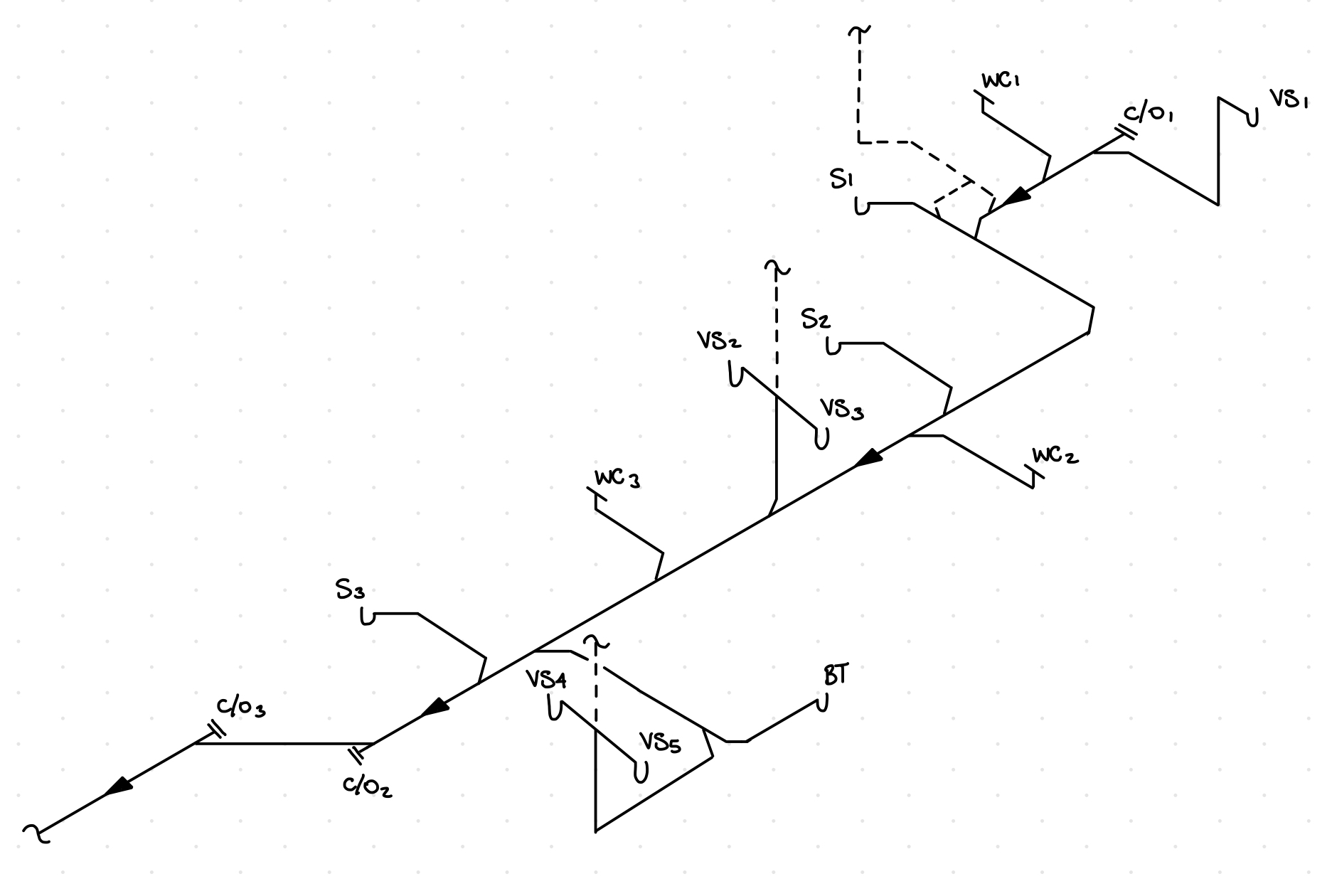
My concerns are mostly around venting. I'm not sure If I've vented the plumbing properly. I used existing vent that were already there in the concrete roof, and eliminated 1 vent right before the S2 symbol, as I only discovered the vent pipe after the fact. The drain between S1 and S2 is new, hence I though Vent1 would suffice.

Please take a look at the diagram below. Are the 2 vents, and AAV enough for the plumbing? If no, where should I place a vent, or preferably an AAV to fix any issues you see?

The main pipe is 3" The shower drains are 2" The Vanity drains are 1.5"

I live outside the US where I don't need to get this inspected, but would still want to make sure what I've done is right. I know I should have asked first, but only recently I thought about it.. Better late than never.

Legend:

c/o: closeout

VS : Vanity Sink

WC : Water Closet

S : Shower

BT : Bath Tub

AAV: Air Admittance Valve

~1 : 1.5" Vent

~2 : 2" Vent

Drain Drawing

Edit: Thanks for the answers, I did not test with water yet.

The flow rate for the toilets is about 1.6 gallon per flush, and the slope of the drains are at least .25" per foot.

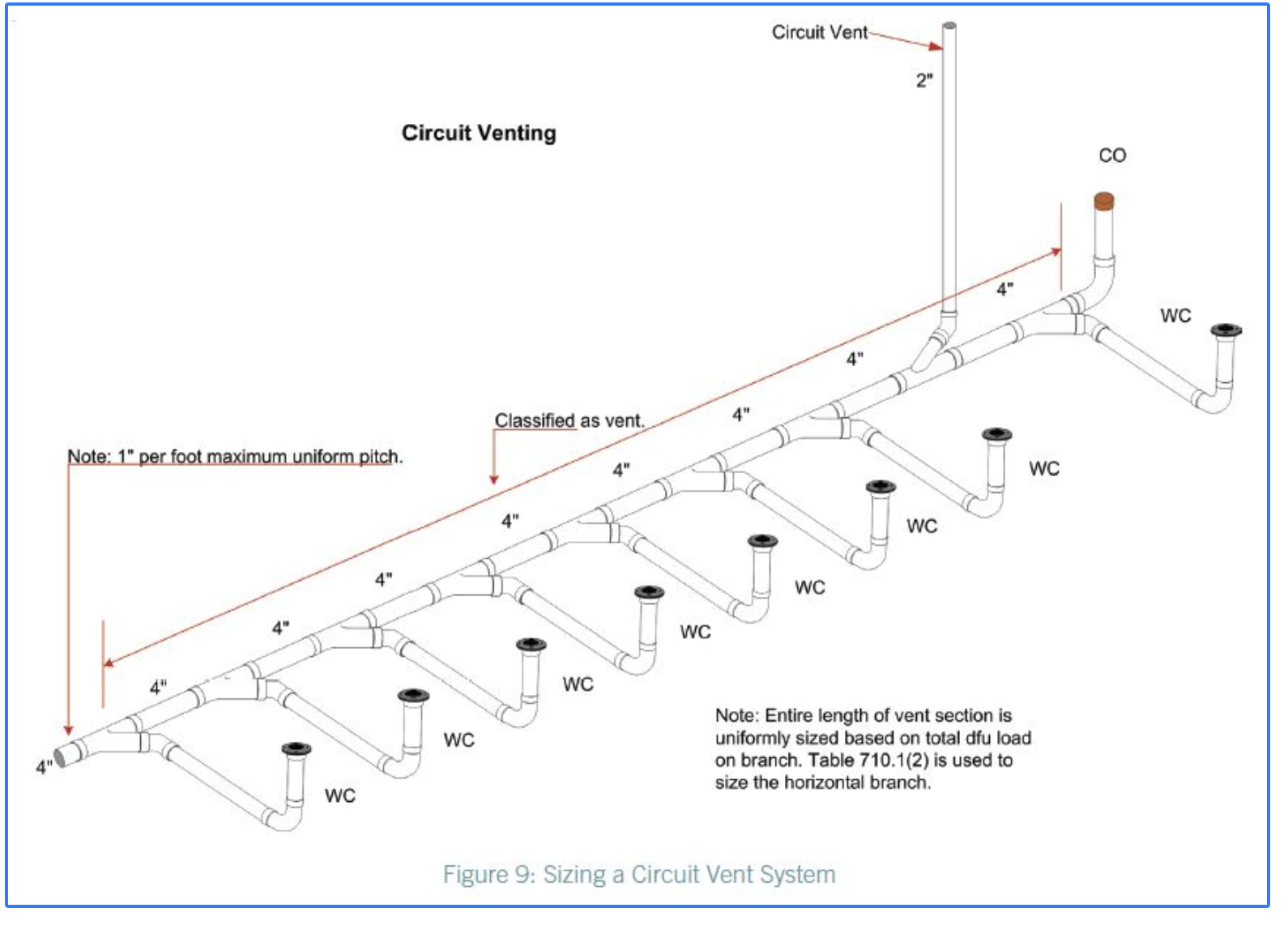
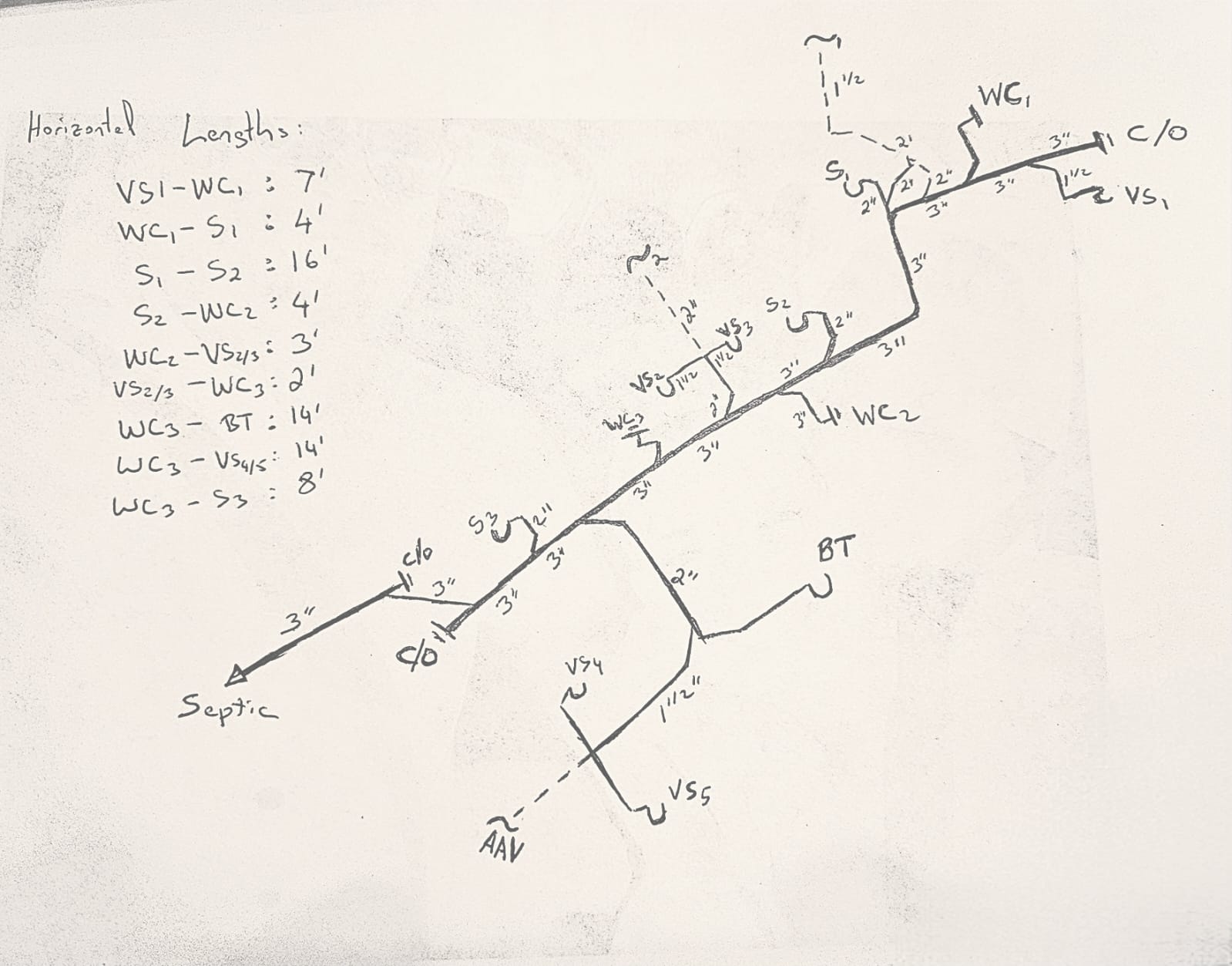
I added the drain sizes and lengths between fixtures. The ones I did not include are less than 3 feet in length. I did do some research, and saw some examples provided for "circuit venting" in the ICC. Here's the link: https://www.iccsafe.org/building-safety-journal/bsj-technical/methods-of-venting-plumbing-fixtures-and-traps-in-the-2021-international-plumbing-code-4/

Based on the diagrams in that link, it seems that having a vent at the onset is the most critical.

Circuit Venting ICC

6
  • Have you put water thru the system?
    – Questor
    Commented Nov 7, 2023 at 22:00
  • Have a nice read. Your local may not apply any code, but this one's "international" so you can feel like it should guide you in the right direction: codes.iccsafe.org/content/IPC2018P5/chapter-9-vents
    – Ecnerwal
    Commented Nov 7, 2023 at 22:05
  • S1, VS1, and WC1 may qualify for a "wet vent" under the IPC, where you would vent VS1 instead of your proposed vent. The toilet would need to be the last drain fixture in the line. Your drawing is too abstract to say for certain what's feasible. I suggest narrowing your question to that bathroom group. Lengths and diameters of the pipes are necessary information for venting questions.
    – popham
    Commented Nov 7, 2023 at 22:19
  • Your drawing is too abstract to determine, but some issues may exist. Sanitary drainage and venting require attention to where and how things are connected. Can you provide an isometric drawing of your system? Something like this: getdrawings.com/img2/plumbing-isometric-drawing-52.jpg
    – pdd
    Commented Nov 8, 2023 at 1:02
  • What's the gallons per flush for your your toilets?
    – popham
    Commented Nov 8, 2023 at 1:45

2 Answers 2

1

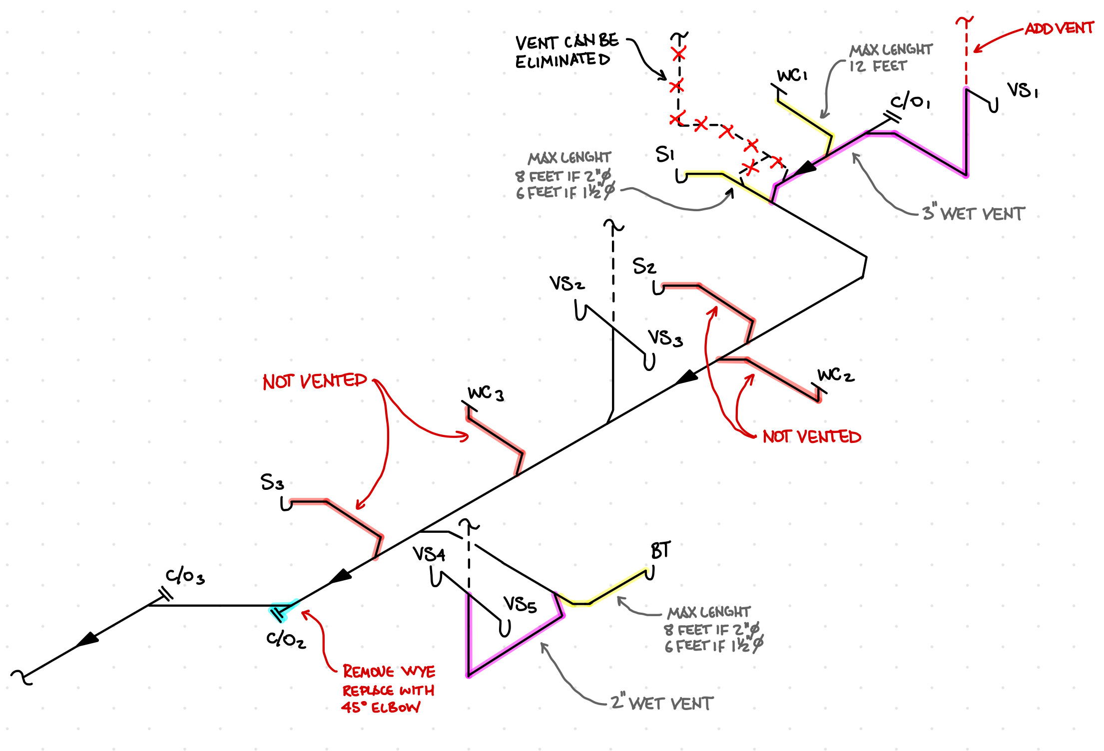
I still have trouble interpreting your sketch. Is this a correct interpretation?

enter image description here

(Three bathrooms, all on the same level)

If yes, then I see some issues with the arrangement.

This would not be considered a circuit vent as it drains more than eight fixtures.

  • VS1 – This would be considered an S-trap and would not be allowed in many areas due to its ability to self-siphon the trap dry
  • WC1 – Not vented (your vent is connected to the branch and not the fixture drain of the WC)
  • S1 – Vented via an individual vent (though some areas do not allow a flat vent)
  • S2 – Not vented
  • WC2 – Not vented
  • VS2 & VS3 – Vented via a conbination vent
  • WC3 – Not vented
  • VS4, VS5, & BT – Vented via a wet vent
  • S3 – Not vented
  • C/O2 – Wrong orientation and will cause blockage

Marked-up Sketch Showing Some Changes:

Note: S2, WC2, WC3, and S3 are still not vented.

enter image description here

6
  • Thanks for such a detailed explanation. If I add a vent in C/O1, would that fix most of the venting issues? Also, do you mind if I store a copy of your diagram?
    – Jef
    Commented Nov 14, 2023 at 18:14
  • Unfortunately, that would not solve anything. The vent in that location needs to be at VS1. Additionally, S2, WC2, WC3, and S3 would still not be vented (I'll add a marked-up sketch to my answer to show this). Feel free to keep the sketch(s).
    – pdd
    Commented Nov 14, 2023 at 20:34
  • I will add an AAV at VS1. Why is S2 and WC2 not vented by vent between S1 and WC1? Same for S# and WC3, why are they not vented by 2" wet vent between VS2 and VS3?
    – Jef
    Commented Nov 14, 2023 at 23:34
  • Also, VS4 and VS5 are using 1-1/2" drain. Is it really a big NO NO to leave it as is, or do I have to break concrete to replace with a 2" pipe? I could alternatively add an AAV at BT. Please ignore if i should not ask, but do you offer virtual consulting services?
    – Jef
    Commented Nov 14, 2023 at 23:40
  • They are not vented because they are connected to the main branch without a vent. VS2/VS3 does not vent them because they are connected to the main branch. This arrangement is neither a wet vent nor a circuit vent.
    – pdd
    Commented Nov 14, 2023 at 23:42
0

For the VS1, WC1, S1 bathroom group, you may be able to wet vent the whole thing with a fixture vent for VS1 (under the International Plumbing Code--the Uniform Plumbing code would not allow S1 wet venting downstream from WC1). If you

  • vent VS1 with a minimum 1-1/2" sized pipe,
  • replumb the drain line between the 3" line and VS1's vent with minimum 2-1/2" sized pipe, and
  • verify that the distance from VS1's vent to S1's trap weir is 8 ft or less,

then the bathroom group is properly vented under the IPC.

Method:

Your toilet is 1.6 gpf or less, so your bathroom group has 5 drain fixture units. For 5 drain units you need a minimum vent size of 1-1/2". For 5 drain fixture units you need a minimum wet vent size of 2-1/2". If the distance between the trap weir of S1 and VS1's vent is less than 8 ft, then the vent satisfies IPC 909.1. The toilet doesn't need to satisfy IPC 909.1 according to its exception.

2
  • Thanks for your answer. It seems I need to add a 2-1/2" vent between VS1 and the first C/O. That's a fairly easy fix. I thought the first vent (~1) between S1 and WC1 would have served that very purpose. Do you mind explaining why that's not the case? It seems similar to circuit venting diagram I shared from ICC. Thanks again!
    – Jef
    Commented Nov 8, 2023 at 11:42
  • @Jef the vent for VS1 is supposed to branch away from the drain line before the top of the sloping drain pipe drops below the elevation of the p-trap's weir. Your downstream vent doesn't satisfy this requirement, so VS1 isn't properly vented. Your detail is effectively an S-trap, where VS1 would siphon the water out of its own trap.
    – popham
    Commented Nov 8, 2023 at 21:27

Your Answer

By clicking “Post Your Answer”, you agree to our terms of service and acknowledge you have read our privacy policy.

Not the answer you're looking for? Browse other questions tagged or ask your own question.