TL;DR
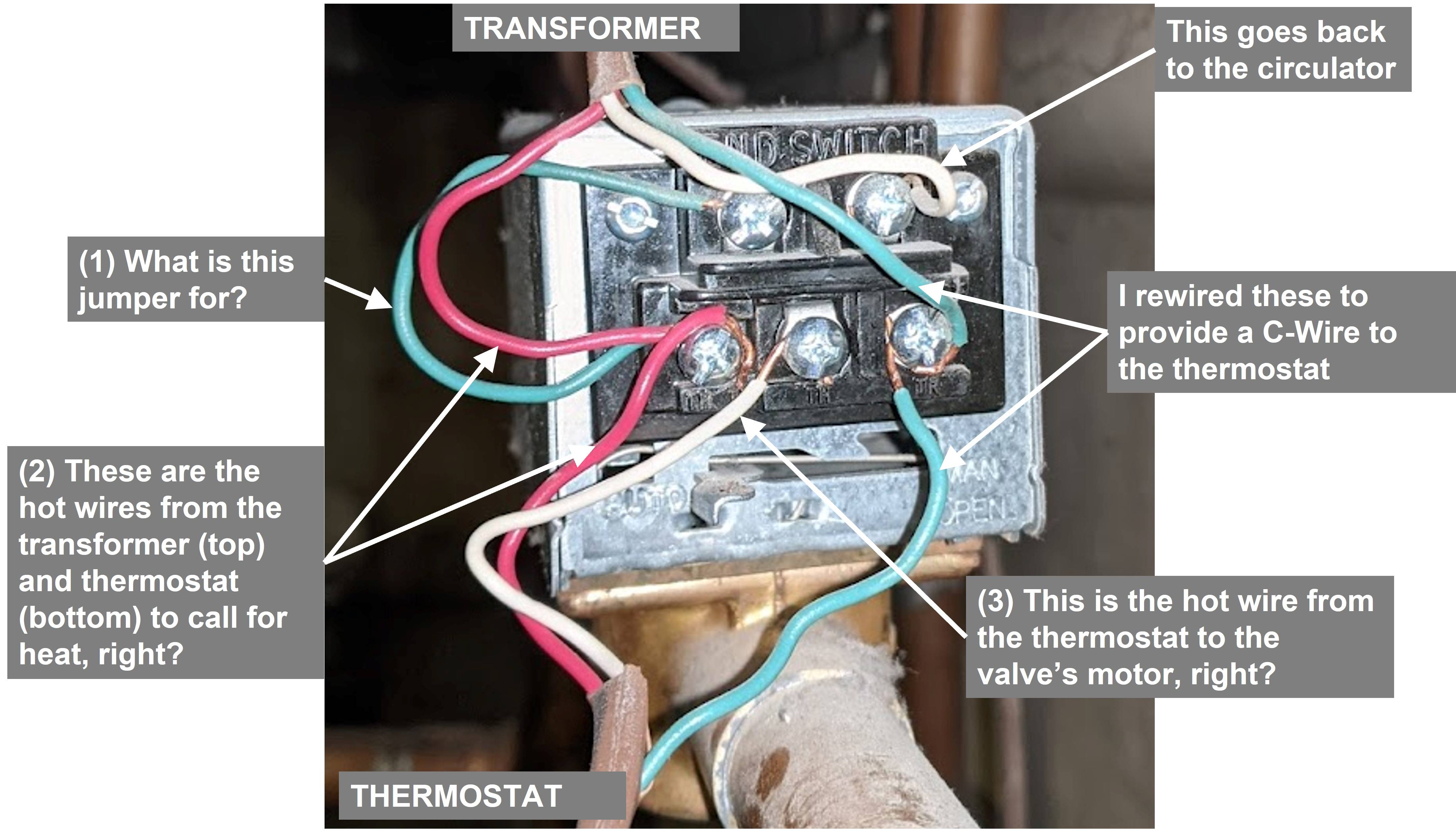
Is a jumper wire necessary between TH/TR and the left-hand END SWITCH?
If so, what does it do?
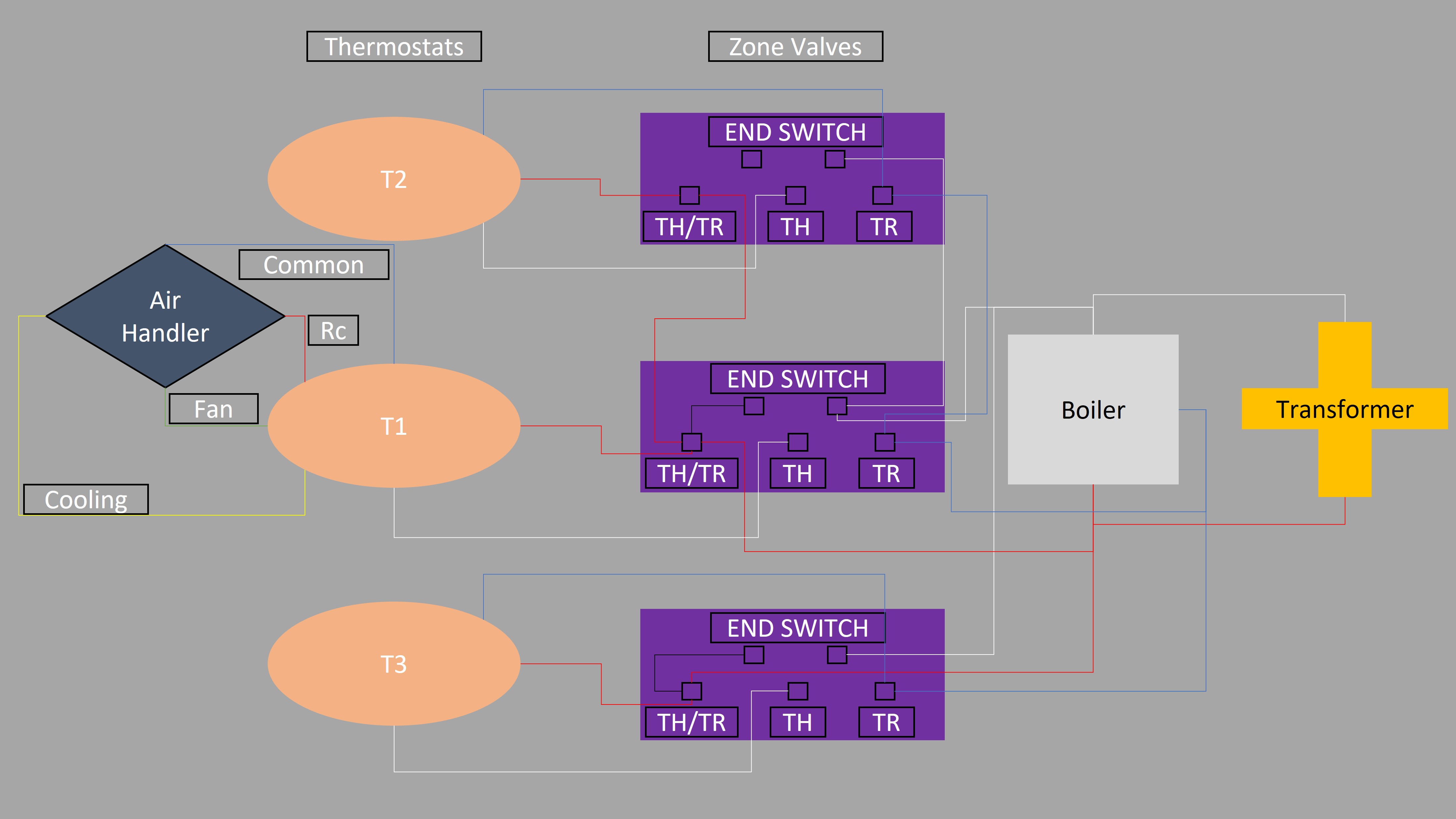
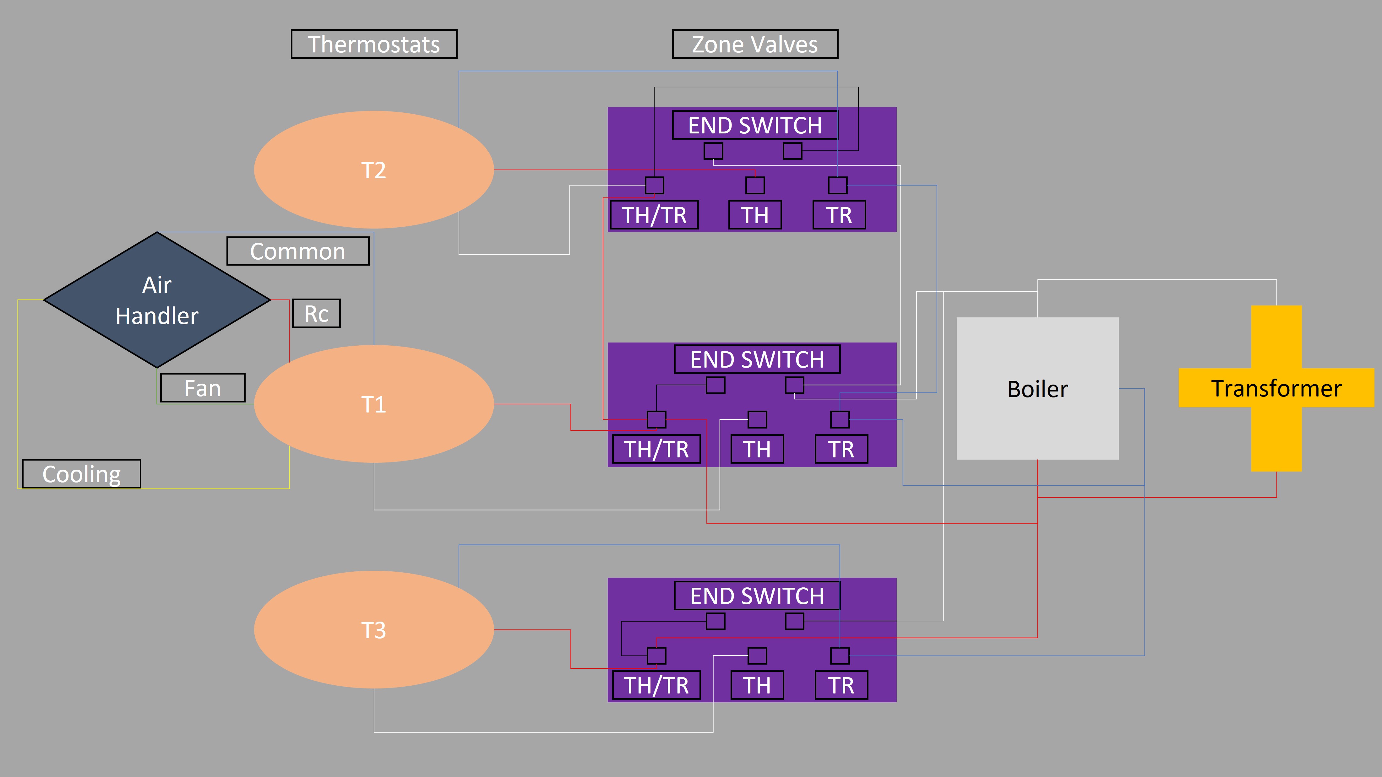
As requested, here is my best approximation of a wiring diagram:
As it is now (note the missing jumper wire in the zone valve for T2):
As it was before I fussed with stuff:
Narrative
I have a 3-zone heating system in my house, with a boiler at the heart. I also have a 2-zone air conditioning system. That's not immediately pertinent, but will become important later (I think).
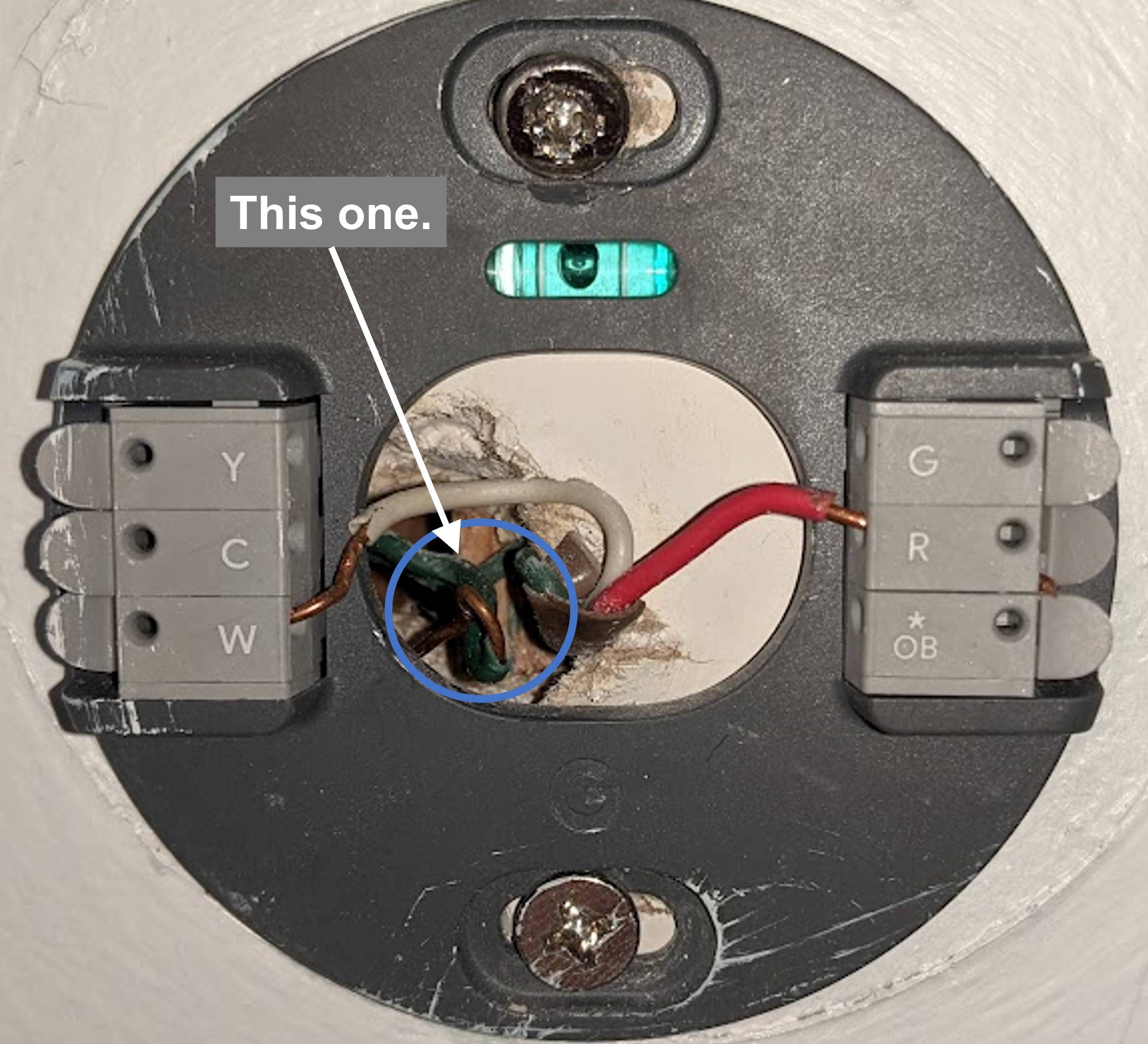
I'm trying to convert an available wire in one of my Google Nest Thermostat 2020's to work as a C-Wire.
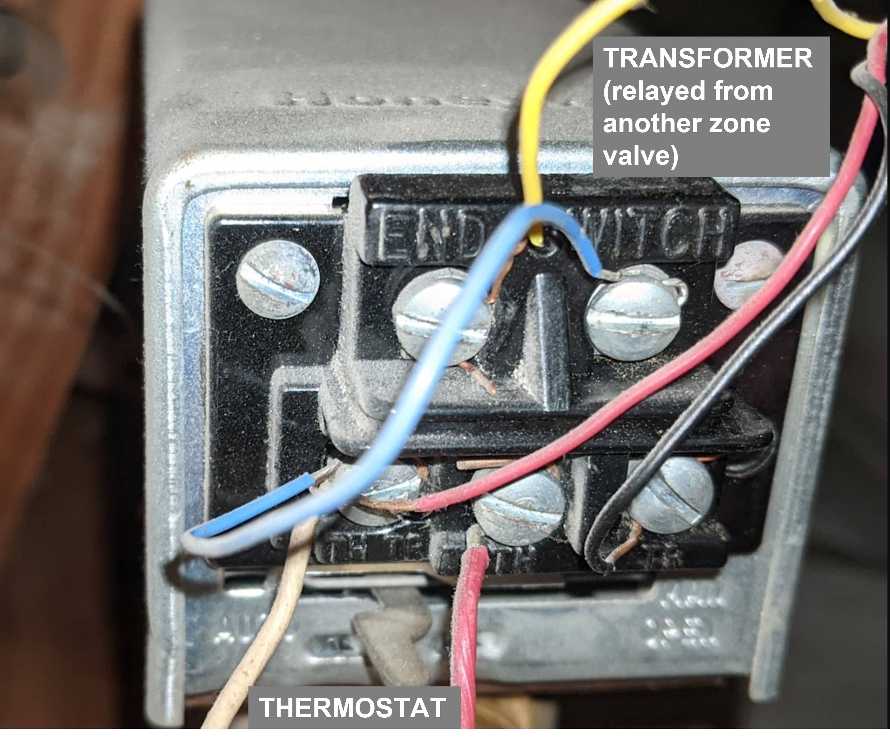
And it is controlled by a Honeywell zone valve with wiring that looks like this:
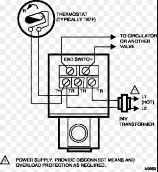
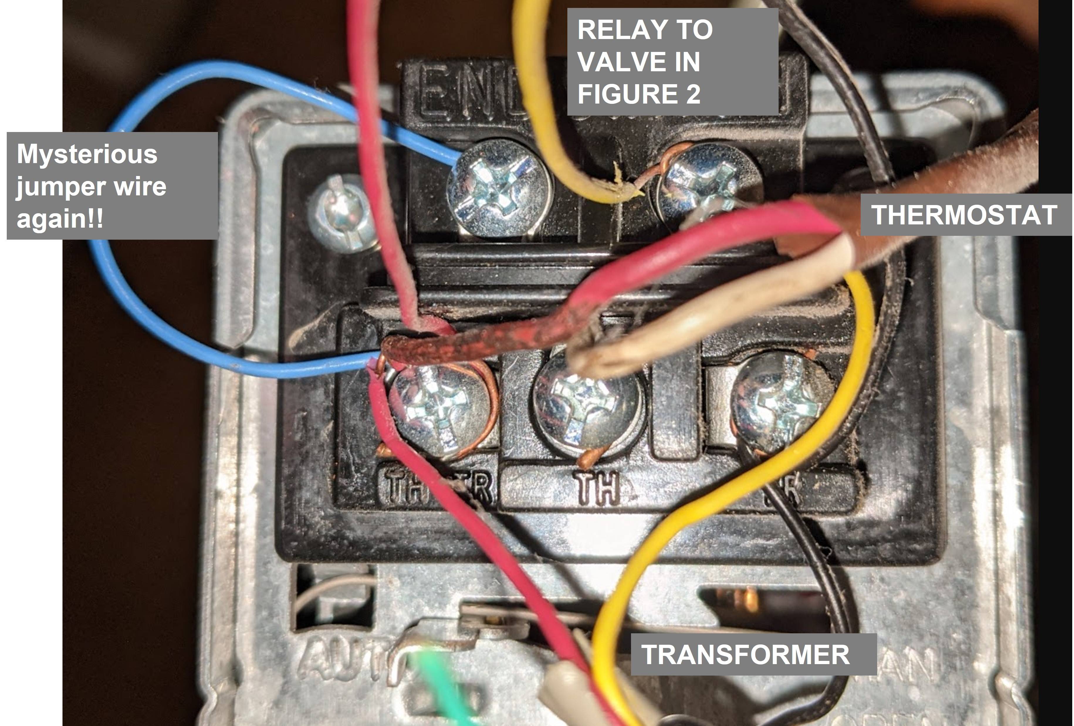
I have already converted a spare wire for another zone valve to power a second Google Nest Thermostat 2020. The wiring at the thermostat was identical to FIGURE 1, with a spare green wire. The zone valve controlling that zone looks like this (FIGURE 3), after my rewiring, with annotations based on the subsequent diagram (FIGURE 4):
FIGURE 4
I don't want to brag, but this has been working out perfectly for the past couple of months. That could be because of my ignorance, and perhaps I'm actively deteriorating my wiring or parts in this zone and it just hasn't caused a defect in the system yet, but ignorance is bliss anyway (just kidding... that's why I'm trying to educate myself; my ignorance is dangerous!).
So, I thought, "I can repeat this process for the other thermostat!" But, of course, as is clear in FIGURE 2, there is no green wire coming from the relay or going to the thermostat at this valve. I believe, given its placement on TR, the black wire from the relay would serve as a C-Wire in this case (FIGURE 2).
Is that the wiring in this valve (FIGURE 2) looks to be at odds with the wiring in FIGURE 3. In FIGURE 2 I've got a white wire from the thermostat going to TH/TR, which also has a red wire coming from the relay. And I've got a red wire from the thermostat going to TH. The yellow wire from the relay is going to the left-hand END SWITCH terminal, while the blue jumper wire is going to the right-hand END SWITCH.
I do not understand the purpose of the jumper wires. Is one way "right" (not going to break stuff) and the other "wrong" (going to break stuff)? Or are they both irrelevant and ignored by the valve?
Now, behind all of this, there is a third thermostat controlling the final zone of heating in the house, with red (Rh)/white (W1) wires coming from the boiler system and red (Rc), yellow (Y - cooling), green (G - fan), blue (currently in C, but see below), orange (disconnected), black (disconnected), and white (disconnected) wires coming from the air handler for the air conditioning system (call back from the beginning!!). That thermostat has its blue wire inserted into its C port, but it reported that it was getting no power from the C-Wire. Turns out I had blown the 3-amp fuse in the air handler when installing the thermostat (I crossed some wires). Anyway, the zone valve for that thermostat's heat looks like this, which is where the relay coming in to FIGURE 2 comes from (note that the red/white/jumper configuration is the same as in FIGURE 3, divergent from FIGURE 2):

