8

We are considering upgrading the service at our office from 100A to 200A because we plan to add more equipment that will be high in power consumption continuously.

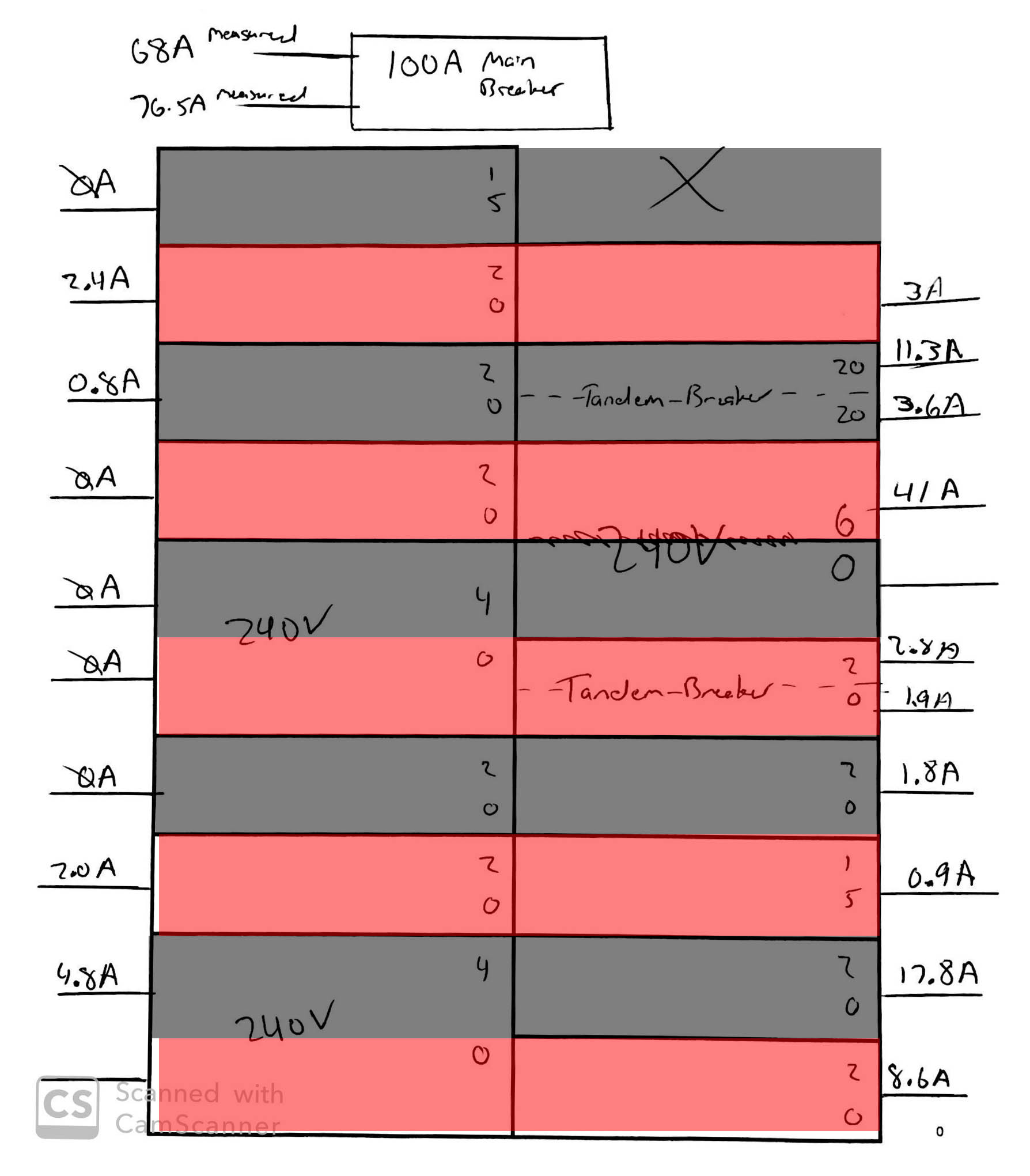
Just to determine where we are currently at before making any expenses, I measured each breaker individually and wrote down all the readings from my Klein Tools clampmeter. The sum total of all the measured current came to roughly 103A. I figured this was odd since if I measure the main breaker at the top, the top wire measured 68A and the bottom measured 76.5A. I assume the difference is due to current leaking through the ground since I can measure 4.4A on the main neutral bus wire.

My question is, unless my measurements are considerably wrong (possible) how can there be nearly 103A total current adding the breakers together but only ~77A through the wire coming into the panel?

Here is a rough sketch diagram of the measurements: Sketch

3
  • 2
    Does this answer your question? Circuit requirements add up to more than 200 amps?
    – Machavity
    Commented Jul 20, 2021 at 14:46
  • 2
    Loads change over time. If you only have one meter, the current you measured on one circuit may be different by the time you measure the main. Lots of appliances cycle on and off. In any case, this is not how you do a service size calculation. You don't need to measure anything with a meter, there are standard ways to calculate the service size and they require you to tell us what equipment you have installed in your house and what the new equipment you're planning to add is. If you're adding a car charger to that panel, you probably need 200A.
    – J...
    Commented Jul 20, 2021 at 15:52
  • Is it possible you misread or double-counted one (or more) of the breakers?
    – Vikki
    Commented Jul 21, 2021 at 16:58

4 Answers 4

20

I'm assuming you're in North America, which means you're on a center tapped supply.

There's a transformer on top of a pole near your house which drops the voltage from the transmission voltage to the household voltage of 240 V.

BUT! They grab one leg from the top of the transformer, and the other from the bottom, and ground in the middle. This means your house is supplied with two legs, each of 120 V.

Those two lines at the top are two separate 120 V legs, EACH rated for up to 100 A.

Half of your circuits are on one leg, and the other half are on the other. What this means, if we don't have any 240 V breakers, is you effectively have two separate supplies of 120 V, up to 100 A. In a pure 120 V world, your 100 A supply is effectively a 200 A supply. (Caution with this metaphor - it's not accurate, but helps understanding).

On your panel, typically, the even numbered circuits are on one leg, and the odd numbers on the other.

This means you can put in a double wide breaker, which spans two slots, and get 240 volts by bridging the two legs.

The tandems split one slot effectively into two, but both are on the same leg.

So, to add up your currents, you need to add up the odd numbered currents, and the even numbered currents separately. BUT the 240s get added to both.

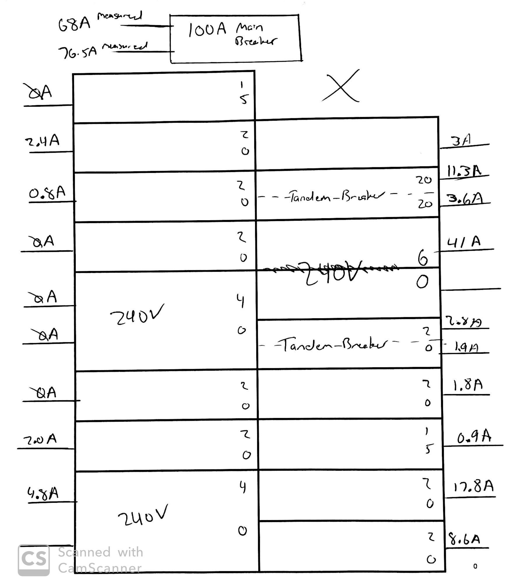
I did a quick guess as to how your panel is configured, and got 81.1 A and 67.4 A. Which is close.

Some 240 W appliances are not pure 240 W. For example, the dryer may have a 240 V heating element, but only a 120 V motor, bridging only one leg of the 240 V circuit This imbalance could be an explanation for the discrepancy on the one leg.

Quick and dirty - The current sum of all circuits should be close to the current sum of the two supply legs. In the case of the 240 V breakers, you'll need to add them in twice, because they affect both legs. I get 148.5 A for the breakers and 144.5 A for the supply, which is close enough given leg imbalances and measurement issues.

11

First of all, while this information may be useful, the reality is that load calculations are, generally speaking, done based on nameplate values of various appliances (water heater, dryer, etc.) plus various "standard" numbers based on type of building, square footage, etc.

But sometimes direct measurements are useful. As noted in another answer, there can be timing issues (though that could be largely eliminated by checking main before/after checking individual circuits), and the difference between the two main hot wires is the neutral. Note that if your overall system is balanced well then those two hots should be close, but they will only be exactly the same if you only have 240V loads (or all your 120V loads happen to match - unlikely).

The total of the two main hots should equal the total of all individual circuit hots.

  • Main hots = 68A + 76.5A = 144.5A
  • Circuit hots = 103A
  • Difference = 41.5A

The answer is the 240V breaker on the right side. You only measured one hot, and it measured 41A. I bet the other hot also measured 41A (it could be slightly off if the circuit serves a 120V/240V device like a typical US oven). Similarly, the last 240V on the left has 4.8A on one hot but no measurement for the other. 103A + 41A + 4.8A = 148.8A. Amazing! Only 4A off, which could easily be due to rounding errors and/or timing.

Back to your original question: 100A vs. 200A. Service size is based on 240V. You are currently (pun intended, of course) using 76.5A (the larger half of your 240V service). That is actually "close" to 100A, because of the way continuous loads are provisioned and other factors. If you plan to add "a bunch of lights and a few computers" then you may be fine without any upgrade at all. If you plan to add some heavy machinery, kiln, welder, big electric heaters, etc. then an upgrade is in order, and 200A is generally the next step up.

Remember that your panel can be larger than your service, but can't be smaller. If your current panel is rated to handle at least 200A then you can upgrade the service and replace the main breaker and then add circuits as needed (and a subpanel if you run out of spaces). If your current panel is only rated to handle 100A (or any size < 200A) then you need to replace the panel in order to use 200A service, in which case the panel can be bigger than 200A, as long as the main breaker matches the service size.

3
  • 4
    Good job noticing the 41 and the 4.8 that weren't noted on both poles.
    – Greg Hill
    Commented Jul 19, 2021 at 20:24
  • For adding currents, if some loads are inductive (e.g. motors) and some are capacitive, they won't be perfectly in phase and won't just add their RMS values, right? Although most household loads are mostly resistive (power factor close to 1), even computer power supplies have some power-factor correction these days. So that could be another factor in accounting for the discrepancy. Or maybe I'm wrong about this, and their currents would add up as far as rating of the main breaker goes, for current flowing between two local circuits instead of on the supply wire. Commented Jul 21, 2021 at 18:44
  • I think they would add as far as this calculation. Power factor determines whether Watts = Volts * Amps or not. Commented Jul 21, 2021 at 18:59
6

There is a little bit of nuance involved in an analysis like this (and I'll get to that in a moment) but probably the biggest challenge you faced is simply timing. It must have taken a few minutes at least to collect the data points. During that time the loads in the building may well have changed. Many loads are automated. Air conditioning and electric water heating both run on a thermostat. Likewise in the break room the water cooler, coffee pot, and refrigerator. Office equipment may change power state too -- a laser printer keeping its fuser warm; an unused PC putting itself to sleep, etc. If you haven't done something to control for all this automation, not to mention people moving about and toggling things on or off, then currents likely changed during the sampling process. That results in a set of numbers that can never balance out perfectly.

Now, about summing the measurements. The lesser of the two currents measured at the main breaker, plus the neutral current, should equal the greater of the currents measured at the main breaker. The magnitude of the neutral current is imbalance. It's 100% normal for that to be non-zero, but it is desirable for it to be near zero. Yours is quite close.

Half of the branch circuit slots draw power from one side of the main breaker; the other half draw from the opposite side. If you study the arrangement of connectors on the bus bars in an empty panel it'll become obvious why this is the case. Figuring out how they add up isn't super-relevant for you at this point. Simply by measuring the currents on the main conductors you can see that much of your system's capacity is in use already.

You (or an electrician) will need to do an analysis to estimate the power requirements of the existing and new equipment. The National Electric Code prescribes a method for this and calls it "load calculation." A web search for that term will lead you to tutorials, worksheets, etc. The completed load calculation will reveal whether your existing service is sufficient, or if not, by how much it should be increased.

1

OK, you have a knowledge gap to understand what you just measured. Let's close it.

First, learn how AC "Split-phase" works - how we get two banks of 120V which can sum to 240V.

Second, learn how the two phases map into the panels.

Third, revisit your own panel armed with this new info.

enter image description here

Now do things make sense?

Your Answer

By clicking “Post Your Answer”, you agree to our terms of service and acknowledge you have read our privacy policy.

Not the answer you're looking for? Browse other questions tagged or ask your own question.