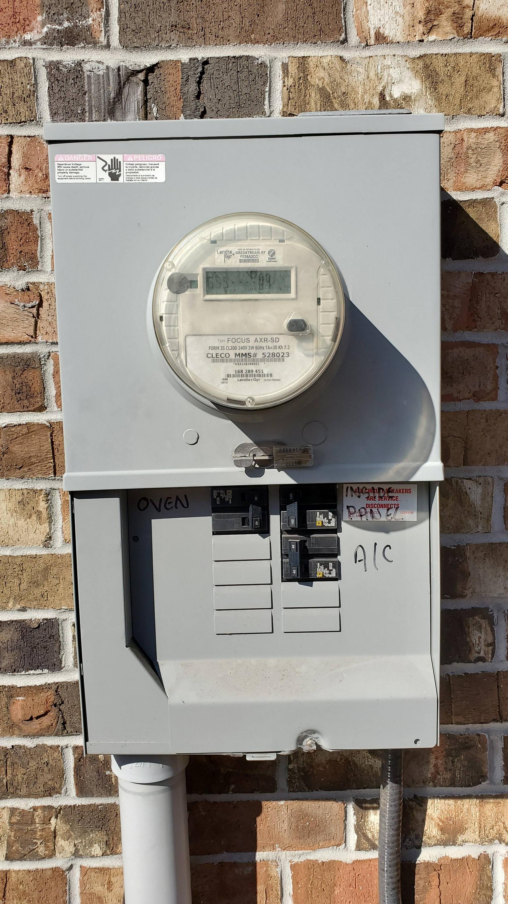
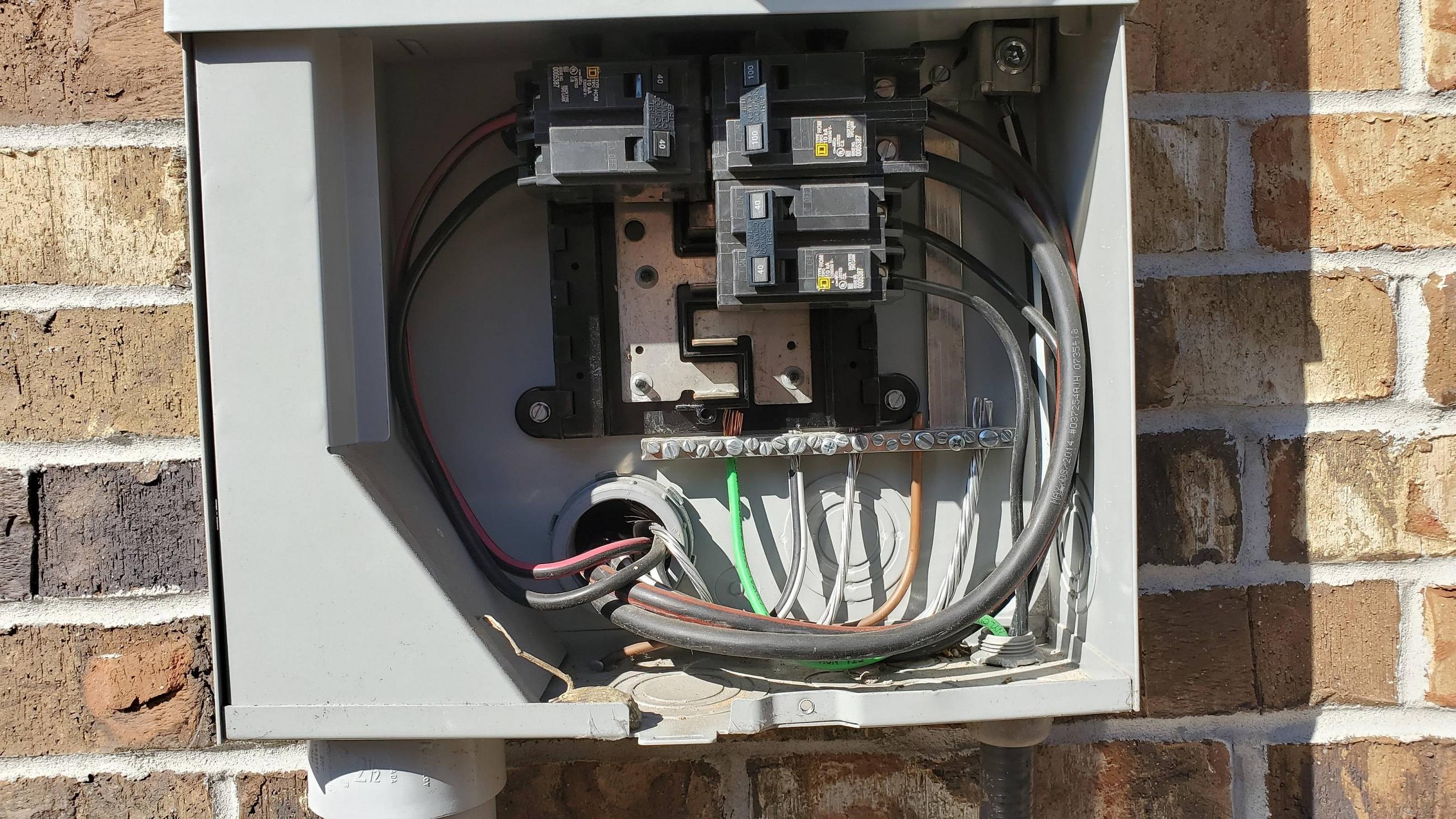
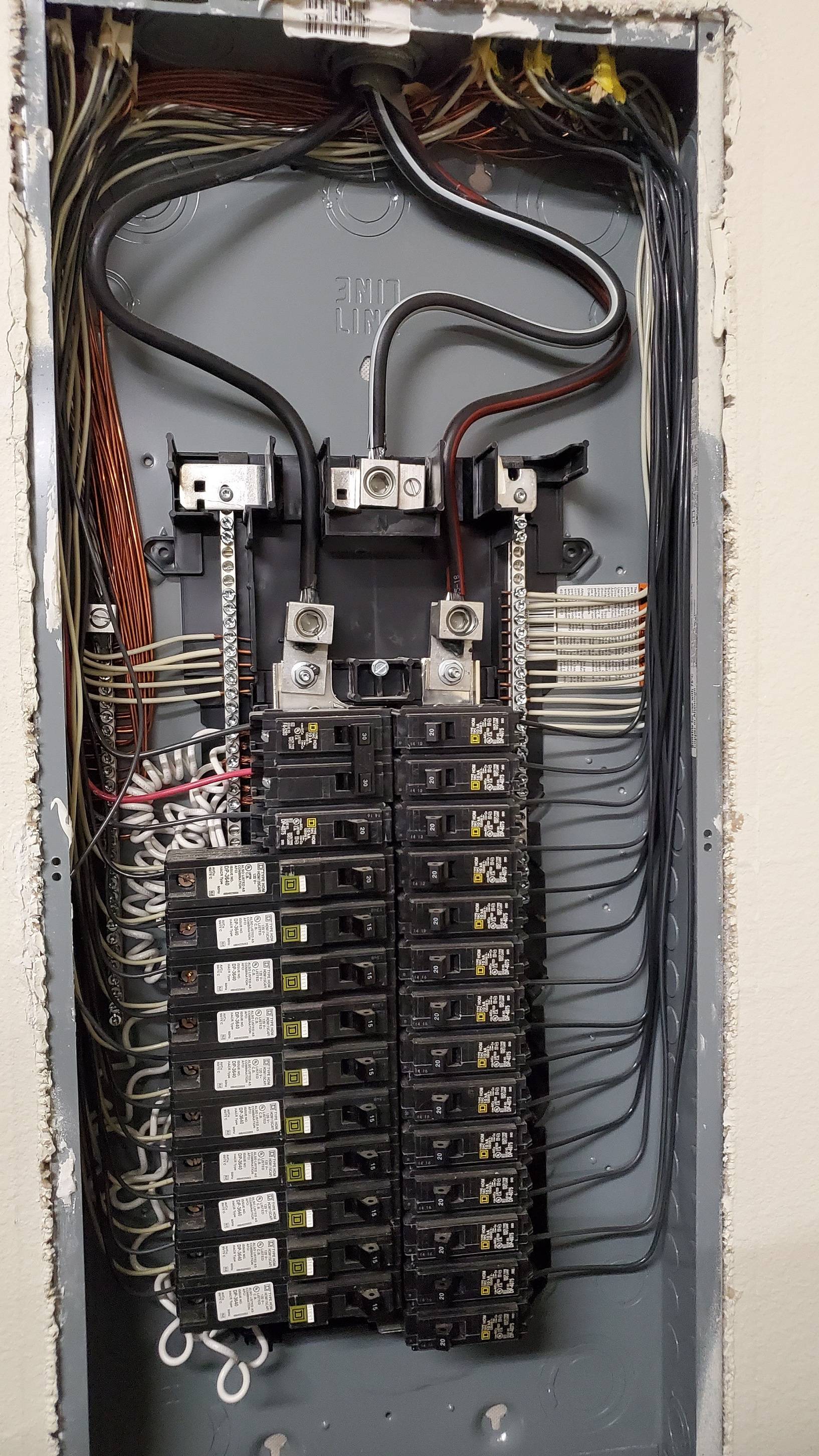
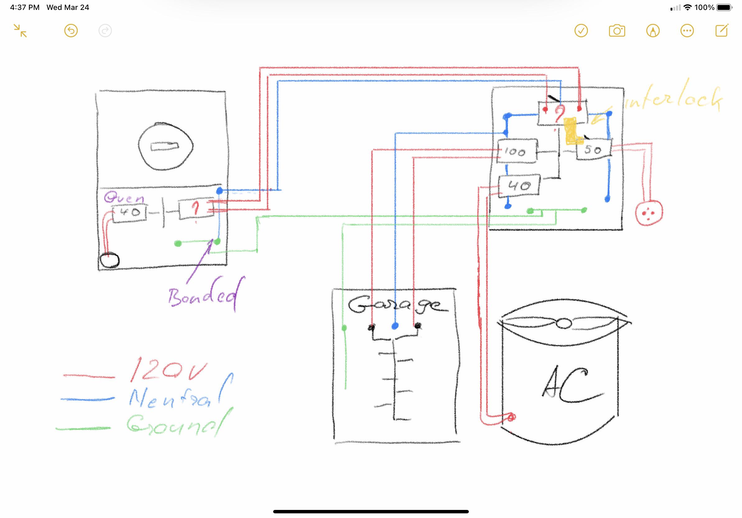
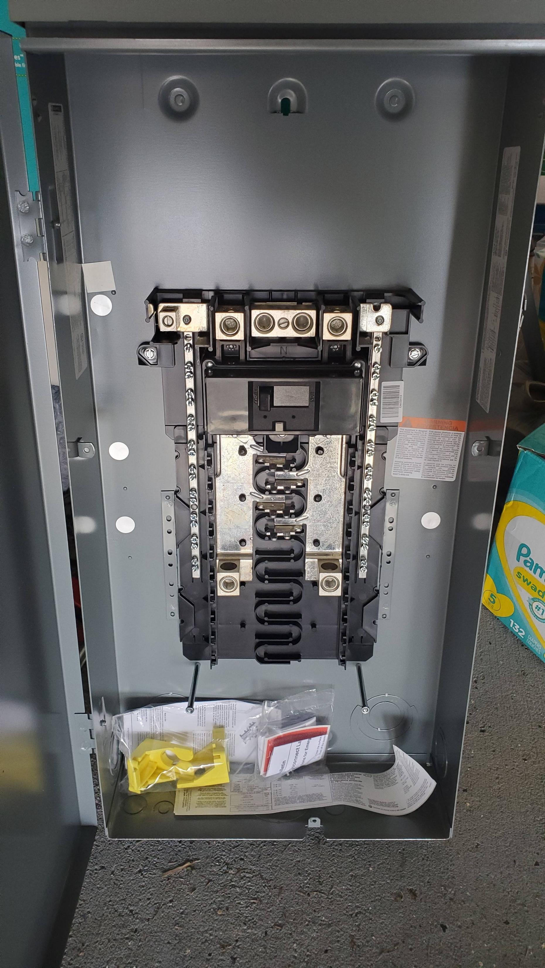
You'll need to take that panel back and get the correct transfer panel for your generator, or else you have dueling banjos bonding screws in your house
The panel you purchased, unfortunately, isn't as useful as you think it is, because in Homeline, like most other breaker lines, you can't use their interlock kits with a bonded neutral generator like yours. This is because there can be only one place neutral and ground come together in your electrical system, but the breakers (interlocked or otherwise) only break the hot wires when switched off, not the neutral.
As a result of having your meter-main's and your generator's neutral/ground bonds in parallel, you'd get wayward current taking alternate paths to get back to where it came from whenever you had the generator plugged in (not even running, just plugged in), which is a NEC violation (see 250.6), potentially dangerous (due to unexpected current on grounding paths), and potentially highly annoying (your AFCI breakers may not like unexpected neutral currents, and will express their displeasure by falsely tripping).
Preventing this, though, is fairly simple at this point. You'll need to take that "mobile home panel" you bought at Lowe's back and order in a switching neutral transfer panel instead. Unfortunately, though, your options are pretty limited here: the Reliance Controls XRH/XRK series panels and a few Eaton CHGEN...SN panels are about all there is out there for this task. Given that you're using Homeline breakers, and want to mount the transfer switch outdoors, I'd recommend the former, with an XRH0605DR providing a relatively low-cost option, while the XRK versions of that panel can be used if you want more expansion "wiggle room".
As to the remaining parts, you'll need a Reliance PK50 inlet kit, as well as a short conduit nipple, 1" in diameter with matching locknuts, some 6AWG THHN (two blacks, one white), and a HOM260 for the utility connection, as well as some NM cable of ordinary (14 and 12AWG) size appropriate for rerouting whatever's going to the generator, as well as ½" NM clamps for that cable, and various sized wirenuts to make connections with.
Lifting the generator's bond
If you would rather do generator surgery than order a switching neutral transfer panel in, that is an option, though. You'll need the panel you recently acquired, a Reliance PK50 inlet kit to provide a place to plug the generator into, some 6AWG THHN (black/white/green) to connect the inlet to the generator breaker, a HOM250 for said generator breaker, a HOMRBGK2C generator interlock kit to keep the generator from backfeeding the grid, a PK15GTA grounding bar for your new panel, a 2" RMC nipple and matching locknuts to connect the new panel to your existing main, some 1AWG Al XHHW-2 wire to make connections, a knockout plug/blank of the correct size for the existing A/C flex KO in the meter main, and a few CuxAl insulated mechanical splices suitable for said 1AWG wire, as well as an inch-pound torque wrench and corresponding torque screwdriver to tighten things down with.
The first step in installing this is to prepare the new panel, starting with the PK15GTA grounding bar. After that, the HOM250 goes in the top right spot, then the HOMRBGK2C interlock is fitted to the panel as per the instructions. With that done, the PK50 inlet kit can then be fitted to the right-side or bottom center KOs on the panel and wired up to its breaker with the 6AWG THHN, while a KO of the appropriate size at the bottom right is opened for the A/C whip to get moved to, and the KO on the left side of the panel is opened up and fitted with the 2" nipple using a locknut on the inside and outside. With that done, two sets of 1AWG Al conductors (hot, hot, neutral) are run from the lugs (main breaker lugs, neutral lugs, feed through lugs) on the new panel out the nipple, creating a 12" "tail" on the main breaker set and a 3-6" "tail" on the feed-through lug set for wiring inside the meter-main. Finally, on the "feed through lug" and one of the neutral lug tails, the mechanical splices get pre-attached, and a locknut is landed on the exposed threads of the nipple so that it'll be outside the meter-main once everything is together.
Remember to use your torque wrench and/or torque screwdriver to tighten the connection setscrews on breaker, panel, and connector lugs/bars to the manufacturer's specified/marked tightening torques! You'll also want to scrape paint off around the knockout on the inside left side of the panel so that the locknut can establish grounding continuity, then touch the paint job up when you're done.
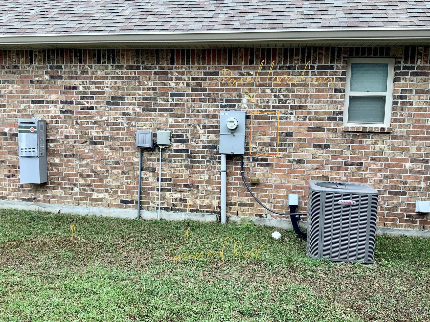
Now, you can install and mount the new transfer box you just built up. You'll want to schedule a power outage with your utility to do this (just call their customer service and ask, most will do it for free during business hours) so you don't have to work around hot busbars in your meter-main. Once the outage starts, you can then knock out the right-hand knockout on the meter-main so that the 2" nipple will fit into it, and disconnect the hot and neutral wires from the 100A feeder breaker and upper neutral lug. With that out of the way, you can then deal with pulling out the 40A breaker for the air conditioning and disconnecting its wires, as well as the green ground for the air conditioner whip.
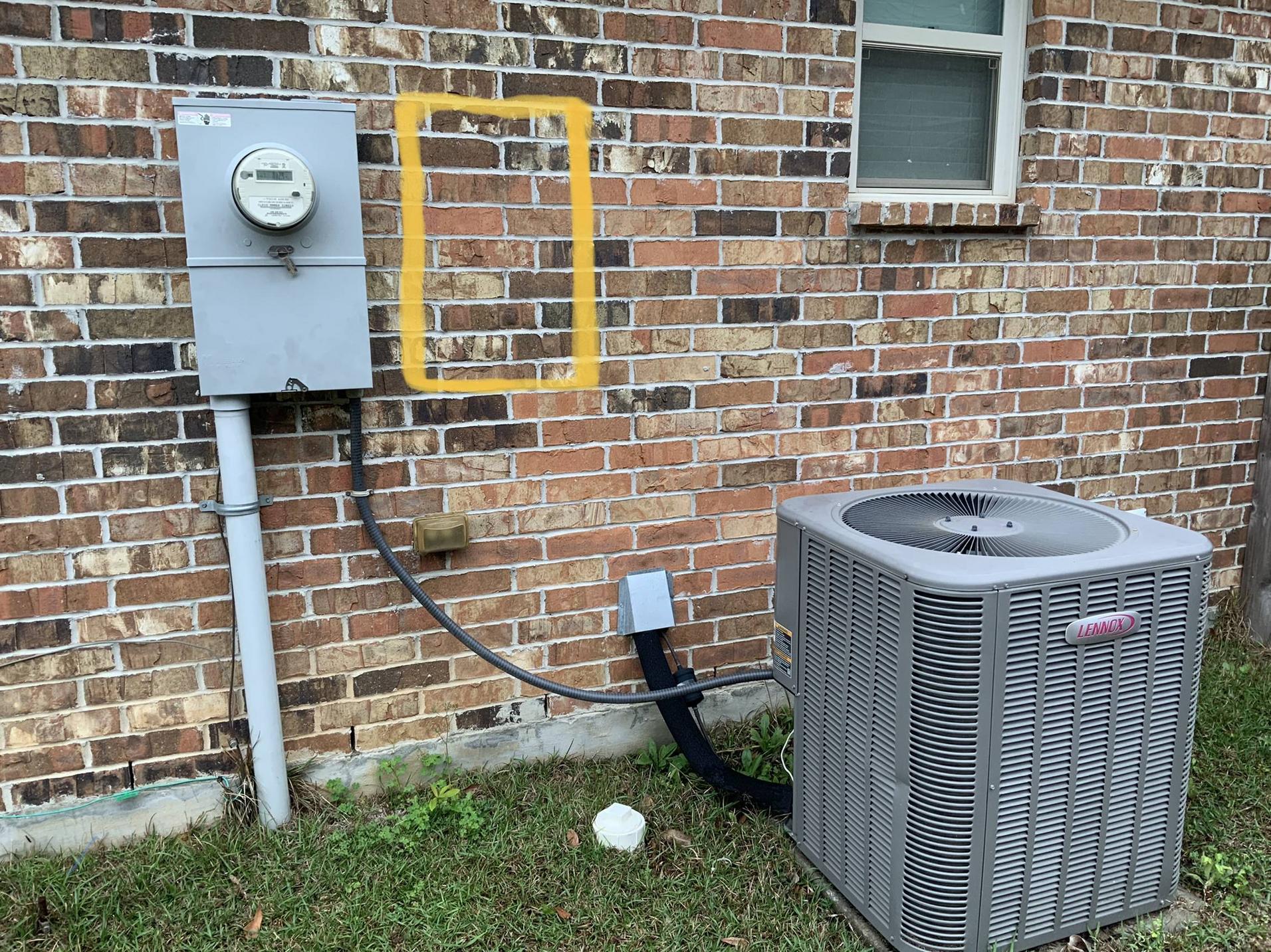
Once you plug the open KO in the bottom of the meter-main where the A/C whip once went, you can then move the 40A breaker to a suitable spot in the new transfer panel. With that out of the way, we then can fit said panel where you have proposed, with the "tails" and nipple fitting into the meter-main via the KO on the right, and the panel mounted in a suitable fashion for your brick walls.
Once the transfer panel is in place, it's time to wire it up to the meter-main. First, the paint around the KO for the nipple gets scraped off, then the last of the 2" locknuts goes into place to attach said nipple to the meter-main. Once the nipple's taken care of, and the paint touched up carefully (no painting conductor ends, lugs, or busbars!), you can then proceed to remove the conductors from the 100A breaker in the meter-main + the upper neutral lug and connect them to the corresponding connectors on your tails. With that done, the "tail" ends that don't have the connectors on them are then terminated on the 100A breaker and the upper neutral lugs, completing the wiring inside the meter-main. Of course, you'll want to use your torque wrench and/or torque screwdriver for making these connections!
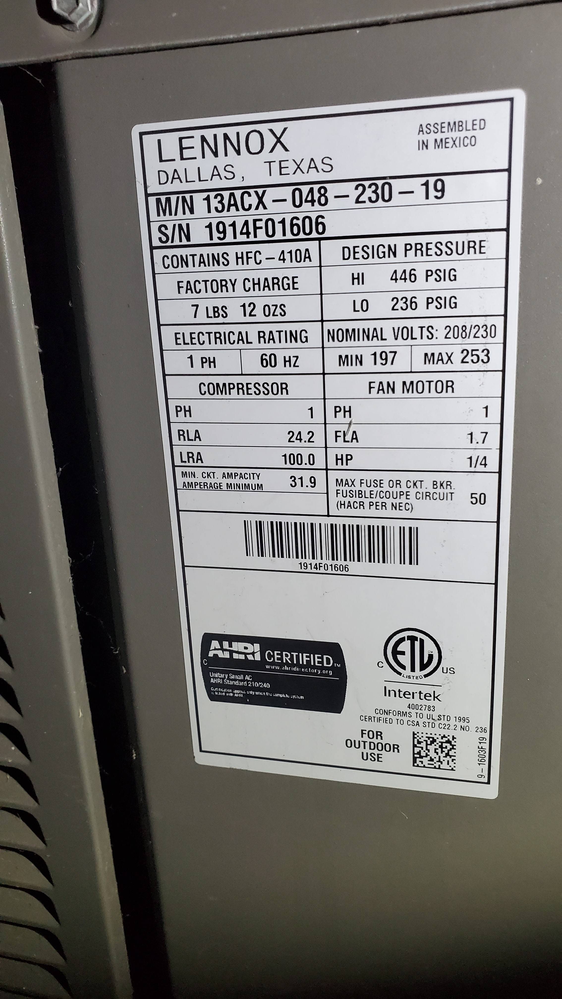
You can now button the meter-main back up and have your utility turn your power back on, as reattaching the A/C can be completed in the transfer box with the 100A breaker that now feeds it turned off. Once the whip's conduit connector is attached to the new panel, the green wire in that whip goes to the ground bar you pre-fitted to the transfer panel, and the two black wires land on the 40A breaker that you moved over. Once again, the torque screwdriver will be needed here so that you torque the lugs on the breaker and grounding bar correctly.
With all that out of the way, you can button the transfer panel up, turn the 100A breaker on, and proceed to remove the bond on your generator. Last but not least, you'll need to label the generator as having a floating neutral in addition to adding the NEC 702.7(C) floating neutral (non-separately-derived system) verbiage to the labeling on your transfer panel.

