2

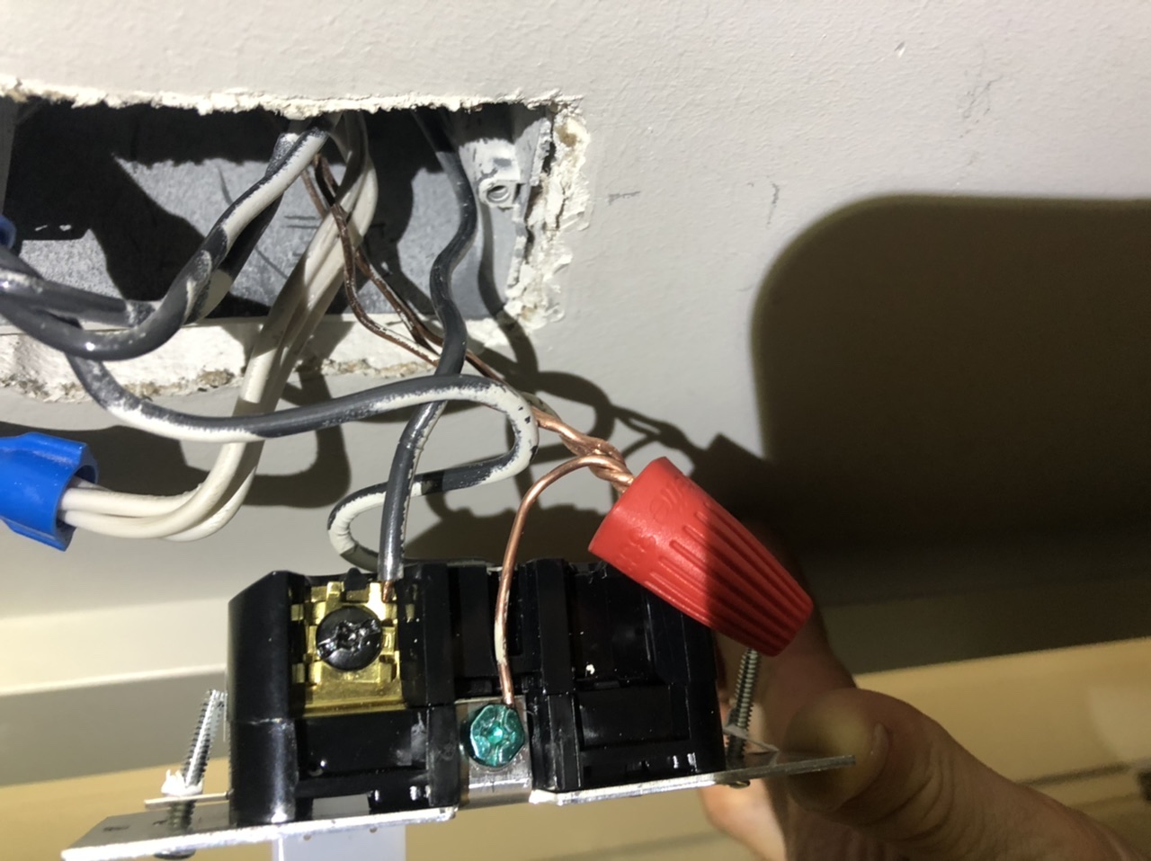
Bought a Leviton IPS02 motion sensor light control. When I wire it as per photo, which is as per instructions, it turns on once when I turn breaker on. Then turns off after timer runs out, the. Doesn’t turn on again. LED flashes when on for first use but does not flash ever again. I’ve exchanged for a new one. Exact same thing happened. I live in a brand new building so assume the ground is working.

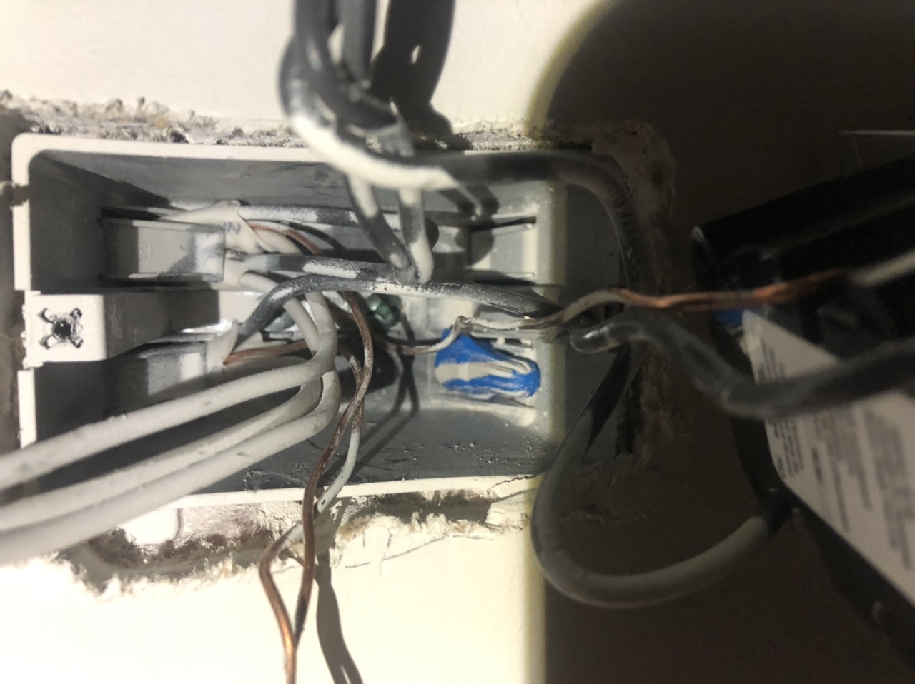
There are 3 lots of cables in the box which isn’t on many of the tutorials etc I have watched or read. Maybe I’m doing something wrong?

enter image description here

enter image description here

3
  • 1
    the photo does not show how the sensor is wired
    – jsotola
    Commented Jul 10, 2020 at 5:53
  • 1
    Great job including a photo, it's amazing how many don't think to do that. However, if you could include 2 additional pics, 1 showing each side of the switch wiring, that would be most helpful
    – FreeMan
    Commented Jul 10, 2020 at 13:06
  • A "cable" is several "wires" in a sheath. It looks like you have 3-4 cables there. That is not unusual, most of them have nothing to do with your project and should be left alone. They are not "spares". That thing where you split the 1 ground wire away from the others, is not cool and you should not have done that. Google "pigtail" for how to add a ground wire, and you'll need a bit of wire for that purpose. Commented Jul 10, 2020 at 14:43

3 Answers 3

2

I see your problem.

Those aren’t “spares”

This happens all the time as people gain experience. They come upon a box with more wires than they need, as you have here. Mentally, they perceive the wires as “The wire I need, plus a bunch of spares”.

What they do not realize is electricians are cheap, and don’t install spare wires. Every wire has a job to do, it’s just a job unrelated to the novice’s project. Usually we see this as someone splitting up a neutral group to grab 1 neutral for a smart switch - which breaks neutral for everything. In this case, you did the same thing, but with ground.

Usually novices do this because the instructions require attaching a neutral wire, and they haven’t accumulated the array of “kit” that an experienced person has - scraps of NM cable for pigtails, variety of wire nuts, etc.

In your case, ditto but ground wire. The grounds you separated need to go back the way you found them. Then, you will need to pigtail off them.

To fix it

Anyway, you are at the horns of a decision to stay with this neutral-less device (that needs ground) or sidestep into a neutral-required device, since you do in fact have neutral here. Either way:

  • The switched-hot wire (typ. Red on device, back on cable) going to the lamp will attach to the 1 wire it’s already attached to.
  • The always-hot wire (typ. Black) will pigtail into a group of black wires, as it probably already does.
  • The neutral if present will also pigtail, being added to the existing group of neutral wires, so all currently-connected wires are still connected.
  • The ground if needed will also pigtail, becoming another ground wire, with ALL ground wires connected to each other.

If you connect all the grounds together with your new ground, then your grounding will be restored, and your device will work as intended.

“All grounds always connect to all other grounds” is a rule. The same is not true for neutral. Sometimes you find boxes with 2 separate circuits in them. Neutral cannot cross between different circuits (grounds can).

Bare AND green wire

Now, a few smart switches have both a green and a bare wire. Read the instructions closely and follow them. In these cases, typically the bare wire is true ground. The green wire is a “neutral if possible, otherwise ground”. These units are designed in a way satisfactory to UL to safely “bootleg neutral” off ground if neutral is not available. Make sure such a setup is approved by an NRTL; this is the last place you want cheap Cheese junk.

6
  • Thank you very much! Spot the newb over here, I’m a carpenter by trade but never really messed around with electrics - probably why I zipped myself twice whilst trying to do this!! Luckily over here it’s only 110v, UK’s 240v hurts a bit more! So from your answer I need to purchase some pigtail nuts to re-pigtail the 3 copper ground wires back together, I then need to purchase some copper wire to add one more wire to this pigtail that will go to my sensor. Would ‘Grounding pigtail with grounding screw’ short wires work? Found on Amazon. Commented Jul 12, 2020 at 1:39
  • 1
    Yeah, don’t buy electrical gear on Amazon, it’s wall to wall overseas junk... even the stuff that’s supposedly sold by Amazon proper often arrives and you find it’s a counterfeit, because of “commingling”. It’s a gorey mess. The local home store has everything you need, and they do curbside. Just buy a combo-pack of wire nuts and a few feet of 12/3 NM-B and cut it up into pigtails. That way you have pigtails of every color. One place I lived in the US the home store actually was called Wickes, but I’ve never seen another. Commented Jul 12, 2020 at 17:52
  • Perfect, yes I shall buy from the local store. I’m in BC Canada and our go to store is Rona, or Home Hardware etc. Thank you for all your advice I will definitely follow through and I’ll let you know how she goes! 😁 Commented Jul 12, 2020 at 18:22
  • So I did the Pigtail for the ground. Didn’t work :( ... I think I give up with this switch. Any suggestions for a switch that doesn’t require a ground as I guess the ground in this building is not grounded correctly or something? You mentioned sensors with neutral connections? This was a $25 switch so looking in that price range. I uploaded another picture to show wiring that didn’t work. Commented Jul 16, 2020 at 3:08
  • @FinnTarget Are you sure you connected all the grounds, every single ground all to each other? Is the junction box metal? If so it also needs a pigtail wire and be brought into this group if it's not already. A neutral-required one should be all over the place. What you already have is the "odd duck"; most sensors are the neutral-required type. Commented Jul 16, 2020 at 4:00
1

The ground is required in this model, some switches pass a small amount of current through the load but this is enough to make LED’s glow. This model passes a small amount of current to the grounding conductor according to the spec sheet. The line voltage should go to the black screw and the load (to the lights) on the screw marked red, other than that adjust the sensitivity pots. If your ground is not connected this switch will not work. A volt meter test hot to ground should show 120vac.

-1

Freeman, I just double checked and I DO get a solid ground, for some reason when I checked AC on the Hot and Ground last time I wasn't getting 124 volts AC, I double checked and it reads 124.9 - 125 volts now. Anyways Let me contribute something to simplify all answers here. I think like mine, you had 3 cables running into the same box because 1 cable is the power from the fuse box or is a part of the circuit that this belongs to, bringing power to this junction box, the other 2 cables are from the nearby outlet, and the other cable is probably your lights, so you have 2 cables which are LOADS.

To wire this to a switch or motion sensor you need to use a non contact probe or multimeter and find your HOT black wire. All white neutral wires get tied together. you must tie your HOT with your OUTLET black wire otherwise the outlet will only be powered when the switch is turned on. add a pigtail to that HOT/ OUTLET and connect it to the switch/ sensor's HOT terminal, next take the wire for the LIGHTS and connect it to the switch/ sensor's LOAD terminal. the wire for the HOT, OUTLET, and LIGHTS are all black, one black wire from each set of cables. When the switch is turned ON it connects HOT to LIGHTS, that's why your lights turn ON. As said OUTLET is always connected to HOT.

To figure out which cable is the OUTLET and which is the LIGHTS simply connect HOT to either black cable from the other 2 wires, whichever becomes powered let you know which cable it's from, you can wire these to a switch if it makes you feel safer. label each black wire for future reference. The reason you couldn't find a tutorial for this is because you have to look for "How to Add a Receptacle to a Lighting Circuit" you are searching for how to add an outlet to a single pole switch which activates a light

2
  • 1
    A) I'm not the one who asked this question. B) are you the OP under a new account? C) Whatever you're trying to say here is difficult to find because there is no formatting. D) Please edit this to make it more readable. E) What did you "double check" and did you really get readings varying between 12 and 125 volts on main power? If so, you need to ask a new question about getting that addressed because that is NOT good.
    – FreeMan
    Commented Mar 1, 2023 at 12:58
  • 1
    Oh, just realized, you're addressing my comment on your previous answer. Please don't delete answers & post new ones to address questions - that (obviously, now) makes it more difficult to follow what's going on. Simply edit your existing answer to clarify the points you're trying to make.
    – FreeMan
    Commented Mar 1, 2023 at 13:00

Your Answer

By clicking “Post Your Answer”, you agree to our terms of service and acknowledge you have read our privacy policy.

Not the answer you're looking for? Browse other questions tagged or ask your own question.