16

A previous owner of my home (I don't know when) wired every room in the house with an ethernet port. I have not been using the ethernet at all, but recent needs for working at home have made me curious about what I could accomplish with somewhat minimal investment.

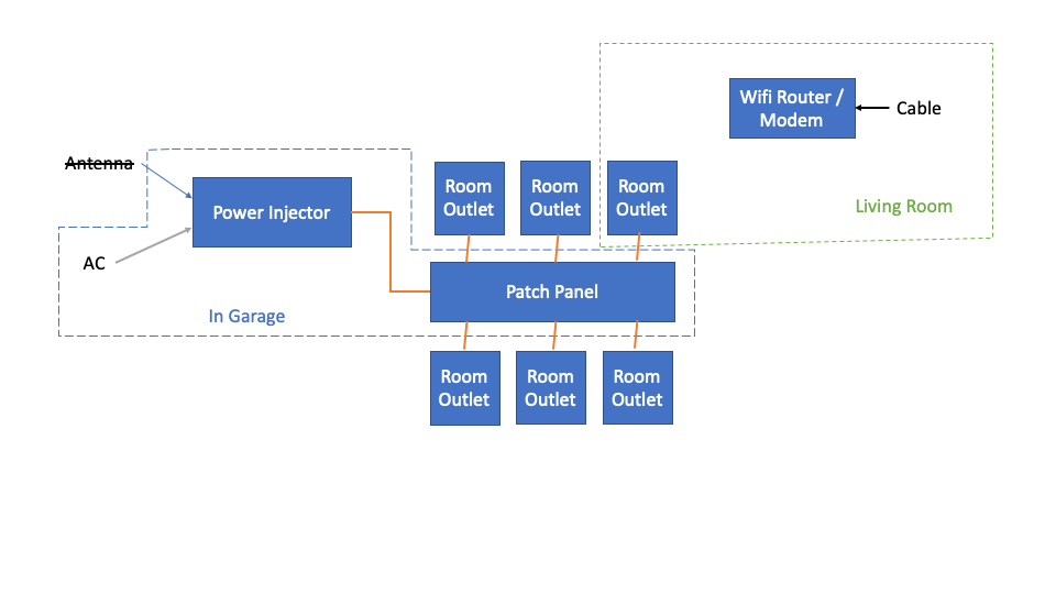
A diagram of what I think is my wiring setup is provided below. There used to be an antenna mounted on my roof with a wire that enters my garage and connects to a "Power Injector" before joining a patch panel. All the rooms in the house have an ethernet outlet that I assume lead to the other wires in the patch panel.

Wiring diagram

Currently, I get my internet from a cable port in my living room that connects directly into an Arris Surfboard cable modem / wifi router.

I am enough of an engineer to feel that simply plugging an ethernet cable into the router and the nearest wall outlet won't suddenly bring wired ethernet into all of the rooms of my house. But in browsing other help pages here and on the wider internet, it's hard to tell what exactly I am lacking.

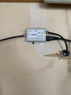
Here is a picture of the power injector.

Power Injector

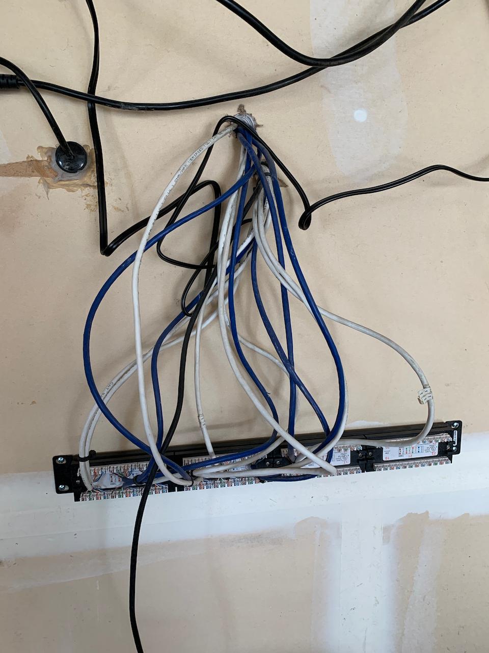
And here is the patch panel (Yikes, I know. Secondary question will be how to figure out which cable in this rat's nest goes where)

Patch Panel

4
  • Can you post some pictures of a wall jack, the power injector setup, and the patch panel? Not sure how an antenna would have tied into ethernet cables. Commented Mar 26, 2020 at 21:11
  • See new pictures added; I can provide a picture of a wall jack later if still necessary. Commented Mar 26, 2020 at 21:23
  • 1
    Better/larger pictures would be helpful. There's a size limit to them, but these are not even close and it's not possible to zoom in to see any details such as actuallly reading the upside down text on the power injector...
    – Ecnerwal
    Commented Mar 27, 2020 at 1:16
  • 4
    "plugging an ethernet cable into the router and the nearest wall outlet won't suddenly bring wired ethernet into all of the rooms of my house." Actually, have you tried this? My parents had this done in '04/'05 for their ranch-style house (office at one end of the house with modem and router)... there's one "out" jack for a cable that goes from the modem to the wall. Other ethernet ports in the house (bedrooms at the other end) were all connected to a switch somewhere (I'm guessing) so we could just plug a hardline into them and it would work.
    – TylerH
    Commented Mar 27, 2020 at 21:01

3 Answers 3

27

Ah, look, my day job...

Step one - if the roof antenna is gone, and you are not otherwise using the existing cables, remove the power injector. It's just wasting power and doing nothing useful, and may be incompatible with whatever you do next. It is at minimum irrelevant, or else it is doing something and you'll notice something like video cameras stop working and revise your assessment of your system wiring.


What goes where?

  • Plug a patch from the Living room (LR) router into the LR wall port.
  • Take a computer to the garage and plug in a patch cable until you find the one (there should only be one) port that works -
  • That port/cable leads to the living room.
  • Label it. (preferably, label both ends - Living room outlet is labelled with port on the patch, patch panel is labeled living room... [or a spread sheet is filled in Port number XX | Living room and then printed out and taped to the wall after it's all filled in - there is usually not room for good descriptive labelling on the panel itself.]

Now, plug another patch cable into the living room port (in the garage patch panel) leaving the living room port in the living room connected to the router.

  • Plug it into any other port in the garage patch panel.
  • Go back in the house and plug a computer into wall jacks until you find one (there should only be one) that now works.
  • Label it (preferable method is as above.)

Repeat until done. If there are jacks elsewhere than in the house, include those. Presumably you can see the wire that leads to the roof and know you don't need to go up there with a computer to find it, and probably don't want to connect it at all. If you have checked every jack you know of and cannot find one that works, note that at the patch panel and move on (there's either some you don't know, or wires are broken/damaged.)


With that done:

You'll probably want a switch in the garage, unless activating only one of the other ports in the house will meet your actual need - that would cost the least.

The best guess I can make from counting wires in the too-small picture is that you have 13 coming in there rather than the 7 your diagram admits to - if you want all of those to work your minimum switch size would be 16. If you only want some of them to work, a 4 or 8 port switch would be less expensive, typically.

I cannot make out from the small picture what obscenity has been done with what appears to be a rack mount patch panel in the garage that's either hanging from the wires (bad, bad, bad idea) or screwed to the wall in what would appear to be a direction that would make the patch ports inaccessible, normally. You can get a small wall mount rack to clean that up rather inexpensively, or even do something creative with blocks of wood and screws that would be better than what little I can infer from the picture.

At that point, your path forward forks a lot depending on what you want and what you have. Personally, I hate having the crappy thing from the cable company doing whole-house WiFi wherever the cable happens to terminate, so I'd either turn that off or turn its power way down and put other WiFI access points (not routers) elsewhere in the house for better distributed signal. With the fancy high speed wireless that runs on 5 GHz, if you can't see the access point from where you are working with your device, your signal will be badly degraded or your device will switch to less fancy and slower 2.4 GHz, since that penetrates walls far more effectively. You may not care, you may be happy with the WiFi (but then why are you even looking at the cables? I suspect you are not totally happy with your WiFi) or you may just want wired connections throughout the house - figure out what you have and what you want and pointing you forward without making assumptions becomes a lot easier.

For instance, it may be a bad assumption that there is Cable-TV coax run to the garage, since the previous method might have been the antenna on the roof being the source of the internet in the house.

Somewhere towards the end of the process, using either screw-attach cable ties or double-sided velcro screwed to the wall (easier to reconfigure without having to cut and throw away all the cable ties) to tidy up that mess of cables would fall under "...in a workman like manner" i.e. not looking like total crud.

13
  • 6
    Far more likely it was powering the radio on the roof, but that's one reason I would prefer larger, clearer pitctures, since I can't make out the labeling on the injector. In any case, it's hurting the power bill at minimum, and may hurt other things if it's a fixed voltage no brains injector as is common in ethernet radios of the old days (not so long ago) - they don't do negotiation before turning power on (it's always on), and they may be some other voltage (24V was common in equipment designed before 48V POE became common - and is still used in some radios even now.)
    – Ecnerwal
    Commented Mar 27, 2020 at 7:47
  • 6
    You've obviously done this before, it shows. And its particularly impressive you didn't suggest "use a tone source" or other similar tools - this requires nothing more than time, thought, and some kind of labeller/sharpie. +1
    – Criggie
    Commented Mar 27, 2020 at 10:30
  • 4
    35 years, more or less... ;^)
    – Ecnerwal
    Commented Mar 27, 2020 at 14:13
  • 1
    And the patch panel was in fact hanging from its wires until a couple of weeks ago... Commented Mar 27, 2020 at 22:34
  • 4
    ...so how do you plan to plug anything into that patch panel? you have the backside facing out (where wires are "punched down" once to connect to the panel) and the jacks/ports (where patch cords plug in) facing the wall with no space to plug in cables, as far as I can see. If you want to screw it to the wall, add some wood blocks to space it out far enough, and flip it around so that you can access the ports/jacks (assuming you don't want to buy a tiny wall-mount rack, which frankly, I wouldn't for my house, though I'll pick one out of stuff headed to the dumpster if I spot it going there.)
    – Ecnerwal
    Commented Mar 27, 2020 at 22:50
7

Anyone notice those silver screws bolting the supposed patch panel face first to the wall?

I don't think that patch panel is what you think it is.

It looks like something that splices together pairs of ethernet cables. Not something that provides rj-45 outlets (a patch panel). These are more common in telephony where the telephone company comes in on the bottom, and your outlets go out on the top. It's not really used much at all for ethernet networking.

BUT you can salvage the situation.

First, make sure it's not actually a patch panel: actual patch panel bolted uselessly face first to the wall by taking it off the wall and checking for rj45 ports.
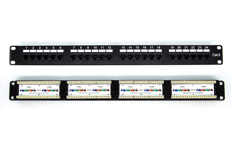
Then you can either buy an actual patch panel and a pushdown tool, and transfer the wires to it. (Remember to trim each wire 1 inch first, untwist, and push down a fresh spot on each conductor. Do not take the easy way out and try to reuse where it's already been bitten. The push-downs depend on the malleability of copper to make a good connection by deforming it during the push)

Or you can crimp them all with rj45 heads. so called home-runs. This is less professional but works just fine in a house. I've 'done the I.T.' for 20 years and used home runs in my home built newly for me a couple years ago. The cables are long enough I could turn it into a patch panel later, but I haven't felt the need.

If you want to go patch panel route you will need to buy the patch panel ($30-ish) and a punch down tool. The cheap kind ($2-3-ish) will do. cheap punchdown tool

And buy short ethernet cables for as many ports as you want to use. $2-3 each

If you want to go home run route, you will need a bag of crimp heads: crimp heads

($10-40 depending on store) and a crimper tool ($20 for a cheap one, and your first one should be cheap if you're not planning to make a career out of this).

Ethernet Crimper

Either way, you should get or borrow a proper tester. I made my last crimping mistake in 2017, but I still test every time. If you've never done crimping before. you should expect every crimp to be faulty the first 5-10 times, then about 50% success for the fifty after that, then decreasing to 5% error rate at 1000 crimps. and to 0.5% a year later, and about halves each subsequent year. I have trained a dozen or so newbies to crimp ethernet on a daily basis.

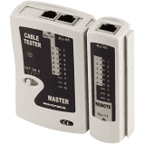
It a tester looks like or resembles this: trash it's trash and you may as well "just test with a laptop" and pretend you don't know that a partially bad cable can still pass data but will negotiate to a lower speed/duplex that will result in packet loss when you're using it heavily.
I recommend the Real World Certifier from Byte Brothers: Real World Certifier This certifier will 'grade' the cable using dozens of RF metrics. There are other certifiers, from Fluke for instance, that cost between 10 and 180 thousand and are more precise. But the RWC is good-enough to be useful at a price that's reasonable for DIY.
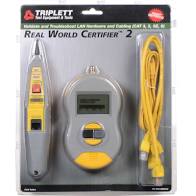
Basically tester=junk. Certifier=good. But I can see that $300+ is a bit much to swallow on a project as small as yours so maybe skip testing and hope for the best.

Any 'tester' that gives you just a single good / not good is junk.

The RWC also has a tracer/toner function that can track down what cable is what without even crimping both ends.

Though I do note what looks like numbered labels in your photo. Those might correspond with a label on or in the jacks in your rooms. Try popping their cover off and looking inside for a matching label.

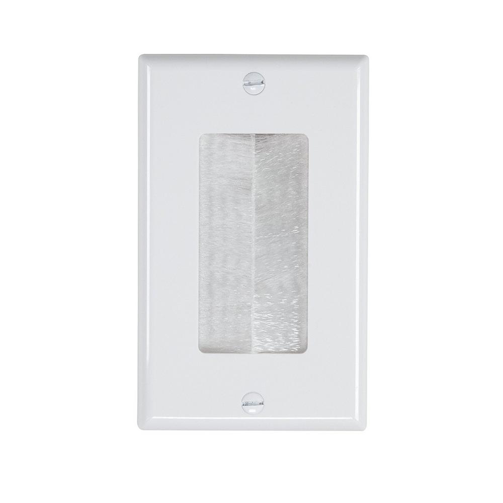
And if you want a cleaner look for your bundle of cables in the garage, you should try a "brush cable pass through": brushed cable pass through I wouldn't bother in a garage or basement. In a finished room if it's in a visible location, sure. Though a patch panel doesn't belong in a finished room in a visible location..... Not in a house anyway.
Once all your 'drops' are crimped and tested, it's time to get a 'network switch' for the garage. In this day and age, I'd recommend nothing less than a gigabit PoE switch. It can provide power to IP cams and ip telephones without bulky external power 'injectors'. I even have entire DVRs that are powered off PoE in my house. You can choose from hundreds of choices on amazon/newegg. Ones with only a few PoE ports would be good as well. Most anything would work in residential.

Then either move the arris router to the garage and link it to the switch (preferred). Or treat the cable from the garage to it as the switch's 'uplink' to the arris, and leave the arris where it is.

8
  • Really? Buy hundreds of bucks worth of certifier for one-time application to a household installation? Plug in devices you already own and see if data moves at more or less the expected speed is a lot more affordable - a $5 pair tester is far more suitable for one-time at home use if you feel the need to waste money on equipment at all... Thank you Captain overcomplicate a simple job and blow the budget....
    – Ecnerwal
    Commented Mar 29, 2020 at 1:44
  • Some peoples' time is worth more than others. But it's really damn handy to know a problem could be fixed by pushing harder on a crimp vs cutting and re-crimping. or worse, if the fault is mid-span (from a stretched or punctured cable), and nothing you do on either end will fix it you won't waste your time trying. Ethernet is NOT as simple as 14-2 NM-B. simple continuity is not enough to work right. For example, a fault could affect the blue or brown pair and a cable would still 'look like it's working'. perhaps the existing in-room jacks are wired backwards. I've seen it in commercial! Commented Mar 29, 2020 at 3:26
  • 3
    The question specifically states "what I could accomplish with somewhat minimal investment." A fault on the blue or brown pair is easily noted for free by observing that the connection is 10 or 100 megabit rather than gigabit. Incorrectly wired jacks are easy enough to spot by visual inspection, rather than the Real World certifier's rather unclear "cable skew error" (why yes, I do use one at work currently, as my current employer's employer requires whole-plant certification.) I'm unimpressed by its failure to communicate swapped pairs as clearly as a $5 pair tester does.
    – Ecnerwal
    Commented Mar 29, 2020 at 13:36
  • Also for free, download TTserver and TTclient, (TT = Throughput Test) put a computer running the server at one end of a cable and a computer running the client at the other end, see how fast data moves (without involving off-site links to internet speed tests, modem speeds, etc.) - or for even less effort, copy a couple of gigs between computers and look at a watch. But finding and using TTserver/client is pretty low effort.
    – Ecnerwal
    Commented Mar 29, 2020 at 13:39
  • 2
    +1 for the numbered jacks, though I think I will not bother with buying a tester/certifier. But if I borrowed one from my office, it's nice to know what to ask for. Commented Mar 30, 2020 at 20:15
3

This depends on the type of panel you have (if it has switching abilities) but generally for a home setup you need to plug router in next to patch panel and then the run an ethernet cable from router to each port/room you want to use.

I would:

  1. Hook router up next to patch panel.
  2. Configure router for LAN access.
  3. Plug a laptop or PC into router directly via ethernet.
  4. Verify that internet works.
  5. Take second cable and plug into a jack on patch panel. If they are not labeled just pick one.
  6. Run to the room on label (or randomly choose rooms if no label).
  7. Plug in laptop or PC to ethernet in that room.
  8. Rinse and repeat through every room. If no labels this could take a while. (especially if you have 16 port for 6 rooms - I would assume ports 1-6 would be on but who knows)
  9. Label your panel.

If the panel has switching abilities you may only need to run one ethernet line from router to panel but based on your description I don't think so. Also if it does have switching abilities the panel may be looking for its internet connectivity on a specific port. (I can confirm yours probably does not have switching ability based on picture but keeping this in here for other who might)

Alternative if there is not coax going to garage.

  1. Keep router in living room.
  2. Set up router.
  3. Plug router into living room ethernet jack. (If there is only one ethernet jack in living room, your living room will have to get its access right from router)
  4. Buy a switch.
  5. Plug in switch into the living room patch panel port in garage.
  6. Configure switch.
  7. Run cables from switch to patch panel.

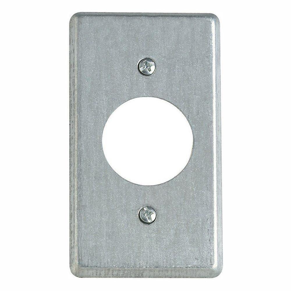
Also not to be totally OCD but put a damn outlet cover on that pile of cables coming out of the wall - below is your $2 solution but there are cool ones out there.

enter image description here

5
  • No you don't need a switch for your patch panel if you have a router. I am guessing you have a run of the mill patch panel and you need to follow my advice in paragraph 1. I will add troubleshooting.
    – DMoore
    Commented Mar 26, 2020 at 21:24
  • Most home routers only have a 4-port switch built in... if you need to connect more rooms than that, you do need an external switch anyway. And even more so if the patch panel is in some faraway place (you still want the router to offer WiFi, no?)
    – user1686
    Commented Mar 26, 2020 at 21:29
  • Curious about moving the router, seems like this would require running cable coax into the garage? Commented Mar 26, 2020 at 21:33
  • 1
    @gregmacfarlane - if they set up this before you I am sure they had coax going to the garage - I guess it could have been DSL... But yes I am sure your router is in the living room for wifi range, it will now need to be in the garage. I will give you an alternative.
    – DMoore
    Commented Mar 26, 2020 at 21:36
  • Picture is really too small to tell, but there's a hint that it may be a conduit, and I hardly think slapping a box cover on the end of a conduit is going to make any functional or meaningful aesthetic difference, but if it would make you happy, feel free. Some drywall compound and paint would appear to be needed for the more obvious damages around the holes in the wall.
    – Ecnerwal
    Commented Mar 27, 2020 at 2:09

Your Answer

By clicking “Post Your Answer”, you agree to our terms of service and acknowledge you have read our privacy policy.

Not the answer you're looking for? Browse other questions tagged or ask your own question.