3

I have a kitchen that has three countertop outlets all on the same branch circuit, and no GFCIs as the house was built prior to that code requirement. My plan was to replace the "first" outlet in the chain with a GFCI and have the other two outlets come off the load terminals so that way all three outlets were covered via the usual setup. Other than having to sort out which was the "first" one in the chain, no big problem.

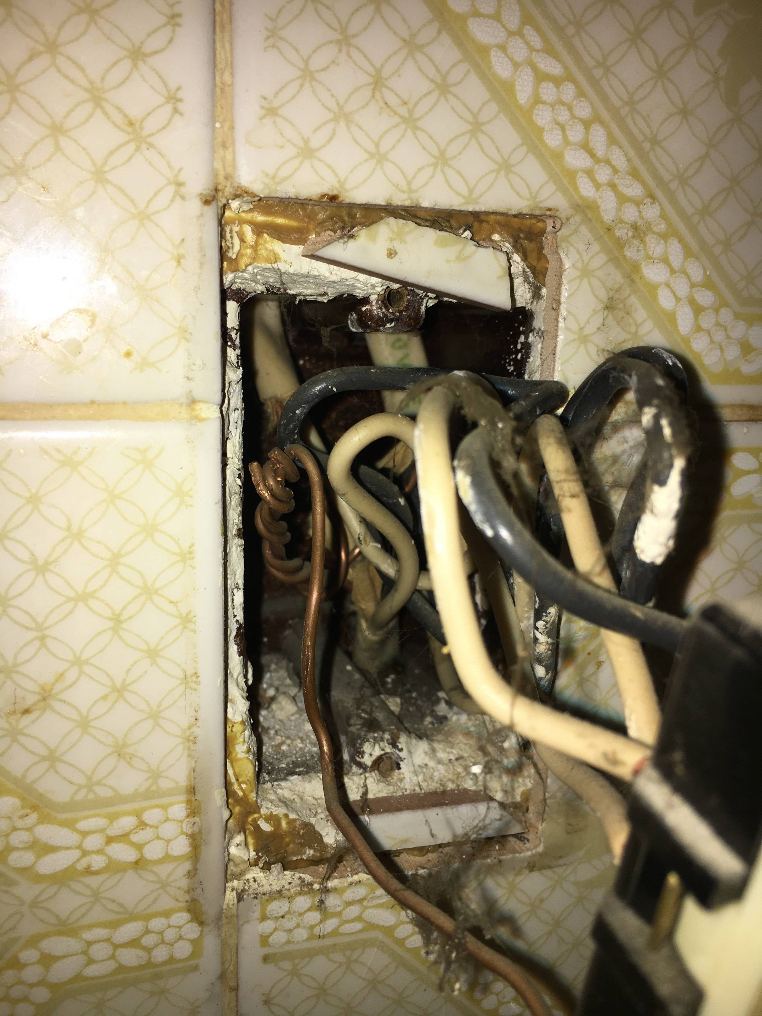
To my surprise once I pulled off the covers, the setup is slightly different: the power from the panel goes to one outlet, and then it has two "forks" that branch to the other two outlets. So one outlet has three 12/2 cables coming in, two of which go to the other outlets. I suspect this is because one of the outlets was installed later and it meant running less cable. It happens that the receptacle that's doing the branching is wired with backstabs only -- three hots and three neutrals adding up to six wires being backstabbed into it. (The wisdom of that I won't question here...)

Looking at the instruction sheet for the Leviton GFCI to see if there were any hints for this sort of a setup, instead it simply says:

DO NOT install the GFCI receptacle in an electrical box containing (a) more than four wires (not including grounding wires) or (b) cables with more than two wires (not including the ground wire). Contact a qualified electrician if either (a) or (b) is true.

So why the "don't do this"? Is this just a "this isn't the easy case and the lawyers didn't want to get sued" or is there some code problem here? My plan was just to pigtail the two loads feeding the other outlets together and attach that to the load terminals of the GFCI. The only particular problems I can think of is either the box just getting too full to work with, or in this case since these are 20A small appliance circuits that a 12 gauge pigtail wire is also required.

Update: So the box appears to be stamped as 16 cubic inches, which means this was far to small even for the existing install. The box does appear deeper than the rest of the kitchen outlets but it's not crazy deep. Ultimately the plan was to replace that box with one to add a switch for a garbage disposal circuit, so I'll probably defer the GFCI install and let the electrician handle that one...and make sure they get an extra deep box.

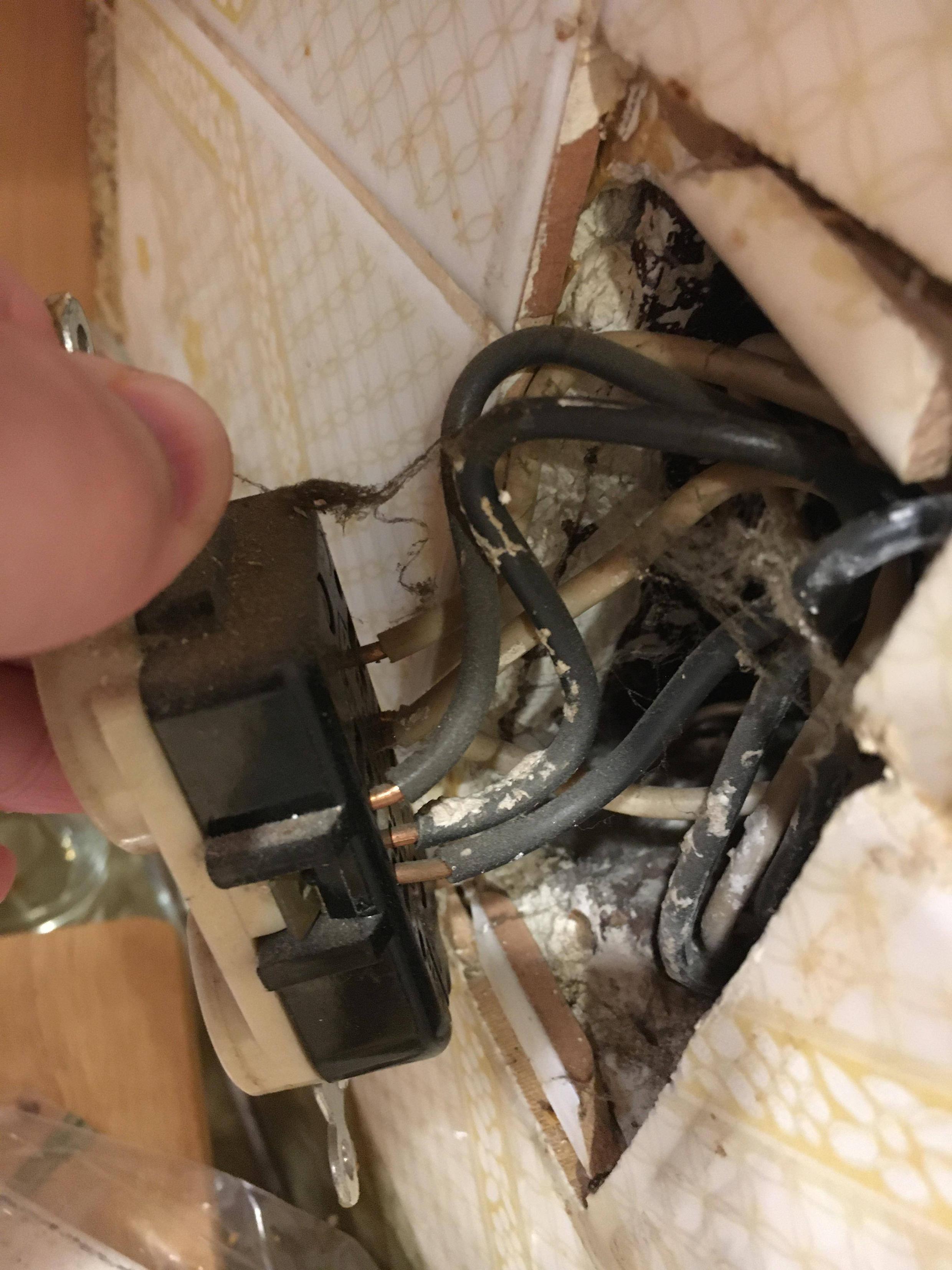
picture of push-ins picture of inside of box

4
  • Are you implying that you would make pigtails out of a smaller gauge wire than the gauge of the wires in the cables entering and leaving the electrical box?
    – Michael Karas
    Commented Oct 22, 2019 at 9:44
  • Can you post photos of the inside of the box in question? Commented Oct 22, 2019 at 11:43
  • @MichaelKaras: nope, but it would have been easy to grab my spool of 14 gauge wire without thinking for the pigtails. I wasn't sure if the writers of the GFCI instructions just didn't want anybody else making similar mistakes. Commented Oct 22, 2019 at 16:44
  • @ThreePhaseEel: photos added, but Ed's answer seems already on the money: this box is too small. Commented Oct 22, 2019 at 17:10

2 Answers 2

3

You are correct the number of wires for box fill is limited by code. I would be feeding the GFCI on the line side and pigtail the load with #12 wire. You are kind of stuck with what you have it’s going to be a tight fit hopefully it is a deep box. I have replaced boxes that were two small with old work boxes and in some cases used a 4 square box with a single device mud ring, this provides the most room but requires a bit of Sheetrock work to close it back up. Each box has the cubic inches allowed stamped on it. To calculate how much you need it’s 2.25 for #12 wire, we only count 1 ground the 3 hot, the 3 neutrals is 7 a 2x for the the receptacle 9 plus if the box has clamps another for a grand total of 10 x 2.25 so the box would need to be 22.5 cu inches to meet code. Hope that helps I believe this is the reason they say no more because standard boxes are not that large and a GFCI device is larger than most receptacles but the same full calculation is used.

10
  • 1
    Maybe a GFCI breaker in the main panel.
    – JACK
    Commented Oct 22, 2019 at 13:02
  • 1
    @JACK, thats possible, but working inside the breaker box is a different comfort level than replacing an outlet. If it's a newer panel, that could be a very good option.
    – JPhi1618
    Commented Oct 22, 2019 at 14:30
  • @JPhi1618 So very true. I always hate recommending going into the panel but the OP might have a box fill problem.
    – JACK
    Commented Oct 22, 2019 at 14:41
  • Probably most contractors use the smallest cheapest boxes available. The panel may be an option depending on type and how full it is now.
    – Ed Beal
    Commented Oct 22, 2019 at 15:43
  • 1
    This whole thing started with me just wanting to replace that outlet by the floor after repainting the wall, discovering it was a MWBC, figuring out what was all going on, and then thinking "well, since I have the breakers off, I had been meaning to GFCI this countertop" only to discover more fun. So much for "let me replace this outlet before dinner". Commented Oct 22, 2019 at 17:41
2

In your case you should either

  • Use a box extender to give you more cubic inches (remember, the wall is proud of the box, and that counts); you could use
    • a $2 metal "handy-box" extension box; not pretty but will fit.
    • a Legrand Wiremold Surface Conduit Starter Kit, which is designed to sit 1-2" proud of the wall and give you a place to launch off surface conduit. You attach 0 conduits :)
  • obtain a 2-pole GFCI breaker for an ITE panel. Apparently Siemens Q series is the direct descendant and is UL-listed for ITE panels. Eaton's CL (not BR) is UL-CLassified for ITE panels, but they don't sell a 2-pole GFCI.
  • Find a location between MWBC split and kitchen where there's already an outlet and fit the GFCI there;
  • Create a location between panel and kitchen to fit a 2-pole deadfront GFCI.

I suspect it's because of NEC 110.3(B), which requires you install according to the labeling and instructions, and the fact that UL approves the labeling and instructions as part of obtaining the UL listing. (or CSA, ETL, BSI, whatevs.)

More than four wires

There are probably two problems here.

Top of the pops is Box fill. There are both practical issues with box fill, and statutory ones.

  • On the practical side, a GFCI outlet takes a lot of space, and can physically "cube out" smaller boxes. On the other hand, larger deeper boxes, such as a 4x4" with a 1-gang mud ring or any of the new-work in-wall boxes metal or plastic, won't have any trouble at all, and this warning would be in error.

  • On the "statutory" side of box fill, you need 2.25 cubic inches per #12 wire and 2.00 cubic inches per #10. All grounds together count as 1 wire, all cable clamps count as 1, and any yoke counts as 2 wires (of the largest size). So a 4-wire situation needs 8 "wires" (16 or 18 c.i.). With 2 more wires you now need 20 or 22.5 c.i.

The second problem with "more than 4 wires" is the ability to use the GFCI itself as a splice point. Most GFCIs I see use an attachment method called "Screw-to-clamp", where the screw acts as a clamp to grip 2 back-feed wires. (not backstabs). That's fine if you have 2 Lines and 1 Load, or 1 Line and 2 Loads - but if you have 3 Lines, you need to pigtail. Pigtailing is beyond the scope of the UL-approved instructions. It's also possible this GFCI doesn't provide screw-to-clamp, and can only accept 1 screw per terminal.

It is common for GFCI instructions to tell you to always attach the onward power cable to LOAD, which I consider a mistake. One should attach nothing to load unless you mean to protect it, because many problems follow if you do not.

3-wire cables

You are warned off of these because these are either - multi-wire branch circuits, which require very special handling of neutral (GFCI or not), and all but forbid use of the LOAD terminals; or - they are switched/split outlets, and GFCI outlets cannot be split.

9
  • This GFCI is this one: homedepot.com/p/… It appears to me you could push in two wires and clamp both down. The instructions are silent on this not saying you can nor can't -- the ominous warning aside. Commented Oct 22, 2019 at 17:43
  • @JasonMalinowski You can't install it contrary to labeling or instructions, NEC 110.3b (the "stop if you see 3 wires or 3 cables" notwithstanding). But the photo looks like it's made for screw-to-clamp, check the labeling. A Leviton certainly ought to be; they invented the thing. handymanhowto.com/electrical-outlets-side-wire-versus-back-wire If not, take it back. Commented Oct 22, 2019 at 17:47
  • Yeah, I agree it looks like it. The GFCI has no physical markings prohibiting screw-to-clamp with two loads, and the "about wire connections" section doesn't say anything special. The only thing that would imply a prohibition is the "contact a professional" warning which as you have well confirmed could be a warning for any number of reasons. Commented Oct 22, 2019 at 17:54
  • 1
    @JasonMalinowski You can see from the link how Leviton does screw-to-clamp. If it looks obviously like it's intended to work that way, you should be fine. The proof of the pudding will be in the firm tug you give it. Commented Oct 22, 2019 at 17:56
  • 1
    Aactually, it appears for an ITE panel, a Siemens Q series breaker is UL-listed, and an Eaton CL is UL-classified for that panel. CL doesn't come in 2-pole GFCI, but Siemens Q does. Commented Oct 22, 2019 at 22:27

Your Answer

By clicking “Post Your Answer”, you agree to our terms of service and acknowledge you have read our privacy policy.

Not the answer you're looking for? Browse other questions tagged or ask your own question.