1

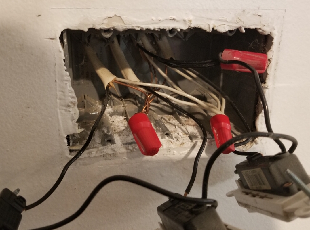
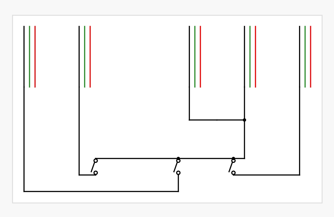
I'm trying to install smart switches, which obviously need a neutral wire. I'm pretty sure I am lucky enough that I have it, but, want to make sure and also find out how to use it. I've attached a diagram of what is inside the 3-gang box that I have.

There are 3 switches that are on the same circuit (all go dead with the same breaker) - one for lights, one for a fan and one for another fan.

The red in the diagram are actually white in the box. Green is ground and black is black. The diagram does not demonstrate this because it would look unnecessarily complicated, but all of the ground wires are bundled together with a wire nut, as are all of the white wires. The grounds are not connected to the existing switches, nor are the white wires.

For now I am just installing a smart switch on one of these.

First, is this possible....are the white ones actually neutrals like I am hoping?

Second, do I just take one of the white wires and connect it to the neutral spot on the switch?

Third, do I need to take one of the grounds out and connect to the switch also? Should the existing switches also get grounds?

Thanks in advance for any advice.

Sorry....forgot the diagram and photo.....
enter image description hereenter image description here

5
  • You don't need to illustrate grounds. In the rare instances that I do, I put them on a separate layer and make them translucent, so they are observable but not obtrusive. A good color for neutral is gray, as that actually is a legal color for neutral. Commented Jan 1, 2019 at 20:06
  • The diagram either describes a strange layout (left & right switches inactive unless middle switch is on) or a different strange layout (power coming "in" from two locations). Which of the items (starting from the left in the diagram) is the incoming (always hot) power? Commented Jan 2, 2019 at 0:05
  • I believe that the two black ones that are connected with a wirenut and then connected to the right switch are live. In the diagram those are the 3rd and 4th from the left (photo it is the 2nd and 3rd from the left). That combined black wire is connected on the switch to next switch in the series at the connection, not after the switch, so I assume, regardless of the switch's position, it continues it to the next switch uninterrupted. So, it seems that there may be two live ins but they are nutted together then chained in series to successive switches before the actual switch.
    – Frank
    Commented Jan 2, 2019 at 0:28
  • @Frank OK. I would make the diagram a little differently to represent function as opposed to the current physical layout. It sounds like diaram "3rd and 4th from the left" are actually one black hot coming in and another going out (to elsewhere - other switches or receptacles in another box) with a pigtail to the switch. Commented Jan 2, 2019 at 2:23
  • That makes sense......thanks for the further clarification.
    – Frank
    Commented Jan 2, 2019 at 18:49

2 Answers 2

1

On the hots, you can add the switch hots via pigtail to that nut with the black wires.

Yes, when all the wires in the bundle are white, that is neutral. Do Not split up the neutral bundle, those are not spare, those are how current returns. The only reason you're thinking that is because you don't have any pigtail wires or wire-nuts on hand and you can't see how to connect without those things. Go get them!

You need to add your neutral wire to the bundle. Since that bundle is pretty full already and I gather you will have 3 smart switches, I recommend adding a white pigtail to that bundle and joining the switch wires to the pigtail with another wire nut.

0

It sounds like this should be a simple change since you have both neutral and ground pigtails in the box. Remove the existing switch with the breaker off. Tie the neutral white to the bundle of whites and the ground for the switch to the ground bundle, the other 2 wires will go to the switch. If there are 3 left on the switch then 1 of those will need to be capped off. Usually black is hot, red is switched hot. The instructions for the switch will usually show a schematic or wiring diagram.

Your Answer

By clicking “Post Your Answer”, you agree to our terms of service and acknowledge you have read our privacy policy.

Not the answer you're looking for? Browse other questions tagged or ask your own question.