1

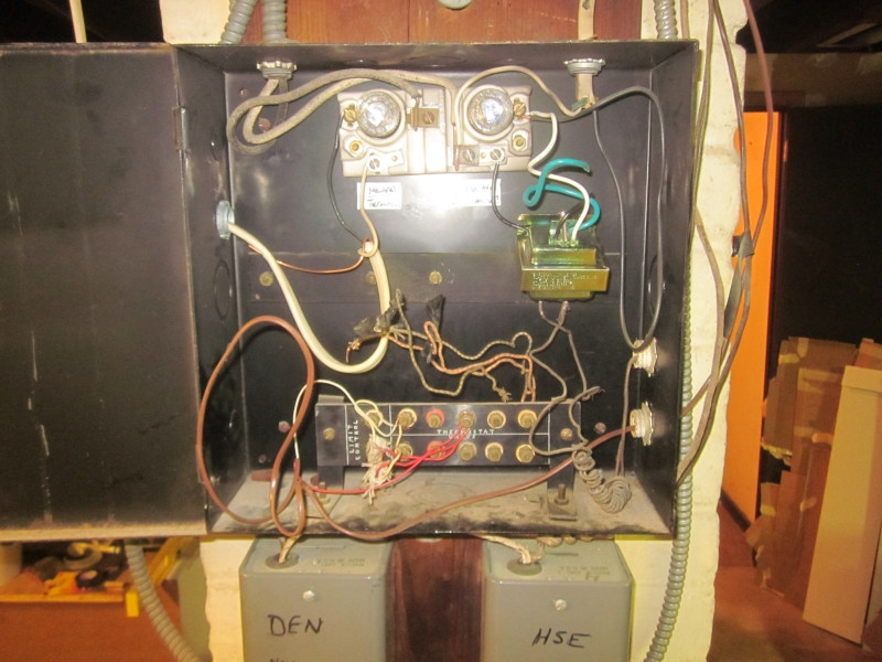
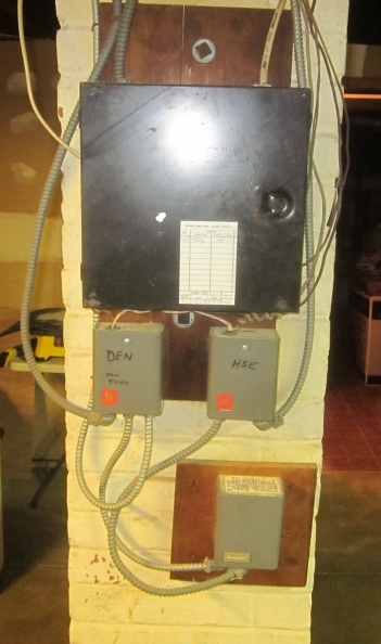
I don't have enough of an understanding of HVAC to know if the pictured boiler fuse box is considered a control panel or a sub-panel - but some wiring issues there lead me to needing to understand more about this setup - and how to handle the unattached ground wires.

fuse box setup fuse box interior

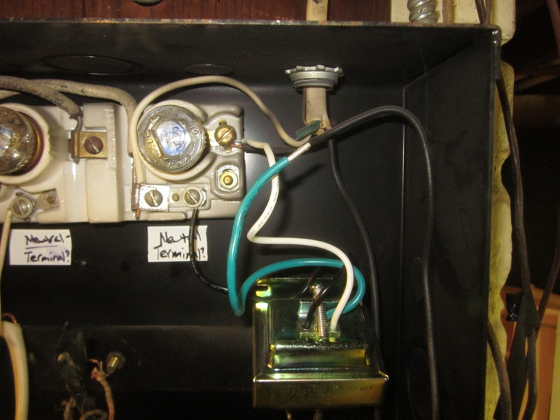
Notice at the mid-left and mid-right there are two grounding wires that are not bonded to anything. One is the NM cable with bare copper that runs to the boiler on-off metal switch box - where it is bonded at that end in the cable clamp. The other is the green wire coming out of the block-like device [transformer].

That same unidentified device [transformer] seems to have it's hot and neutral wires reversed at the ceramic fuse block: the white wire tests "hot" with tick tester, same as another black wire terminated there.

Reversed wires? Transformer connections

Both the cables that feed this fuse box (20 A), and the devices below it (pump relays?)(15 A), are old "BX" and do not appear to contain any bonding strip. The junction boxes they originate from are bonded to grounding wires that run back to the main panel box.

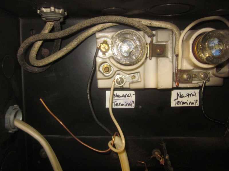
That ceramic block that holds two 15 A fuses appears to isolate the neutrals from any ground connections in the box - if they'd been connected. As it is, it appears the only grounding means is via the armor of the BX cables.

Ceramic fuse block

So how should I handle the unattached ground wires?

If anyone is open to discussing the control panel at the bottom of the box I'd love to add some more pictures and also ask about that. Even a link to a resource that educates about a setup like this would be appreciated.

6
  • 1
    The box is a transformer and both that green wire and the ground should be bonded to the metal case. I am not sure why they reversed the black and white on the transformer (it doesn't matter to the transformer) but I would swap them so someone else doesn't get confused.
    – Ed Beal
    Commented Oct 25, 2016 at 18:25
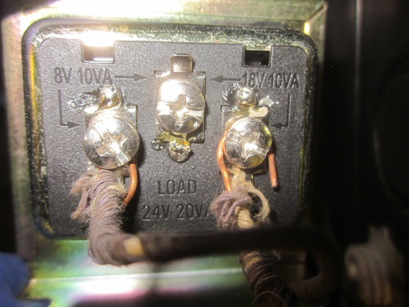
  • Thank you, sir. I just added a pic showing the bottom of that device and the two small gauge wires that connect to it. They appear to run out to one of two thermostats in this two-zone system. I haven't followed them all the way yet. Is it possible this transformer is powering both thermostats in the system - is that something that's commonly done? Commented Oct 25, 2016 at 18:45
  • 1
    That transformer supply's the voltage needed for the system, 24v they are very common. Many times the voltage they supply is rectified to D.C. for control boards, in your system it is probably used to control a 24v relay. The reduced voltage in the controls is safer and less expensive than using line voltage.
    – Ed Beal
    Commented Oct 25, 2016 at 21:56
  • 1
    This is not a subpanel by the strict definition of the term -- it's closest to an Article 409 industrial control panel. Neutral and ground should still be separated in an Art. 409 ICP though! Can you get us better photos of this setup? Commented Oct 25, 2016 at 22:31
  • Sure thing, I have plenty of photos. What would you like a closer look at? Also, mystery of that transformer is solved: it's for the doorbell. Commented Oct 26, 2016 at 3:30

1 Answer 1

1

Add a ground screw and land the ground wires there

I'd use a self-tapping ground screw (Garvin GSST or equivalent -- these are different from regular sheet-metal screws in that they use a fine-pitch (32tpi) thread instead of the 16tpi coarse pitch thread normally found on a sheet metal screw) into the back of the box to provide a grounding point, then land the loose ground wires there. The fact that it's only grounded via the BX armor is not great, but it's better than floating altogether....

Your Answer

By clicking “Post Your Answer”, you agree to our terms of service and acknowledge you have read our privacy policy.

Not the answer you're looking for? Browse other questions tagged or ask your own question.