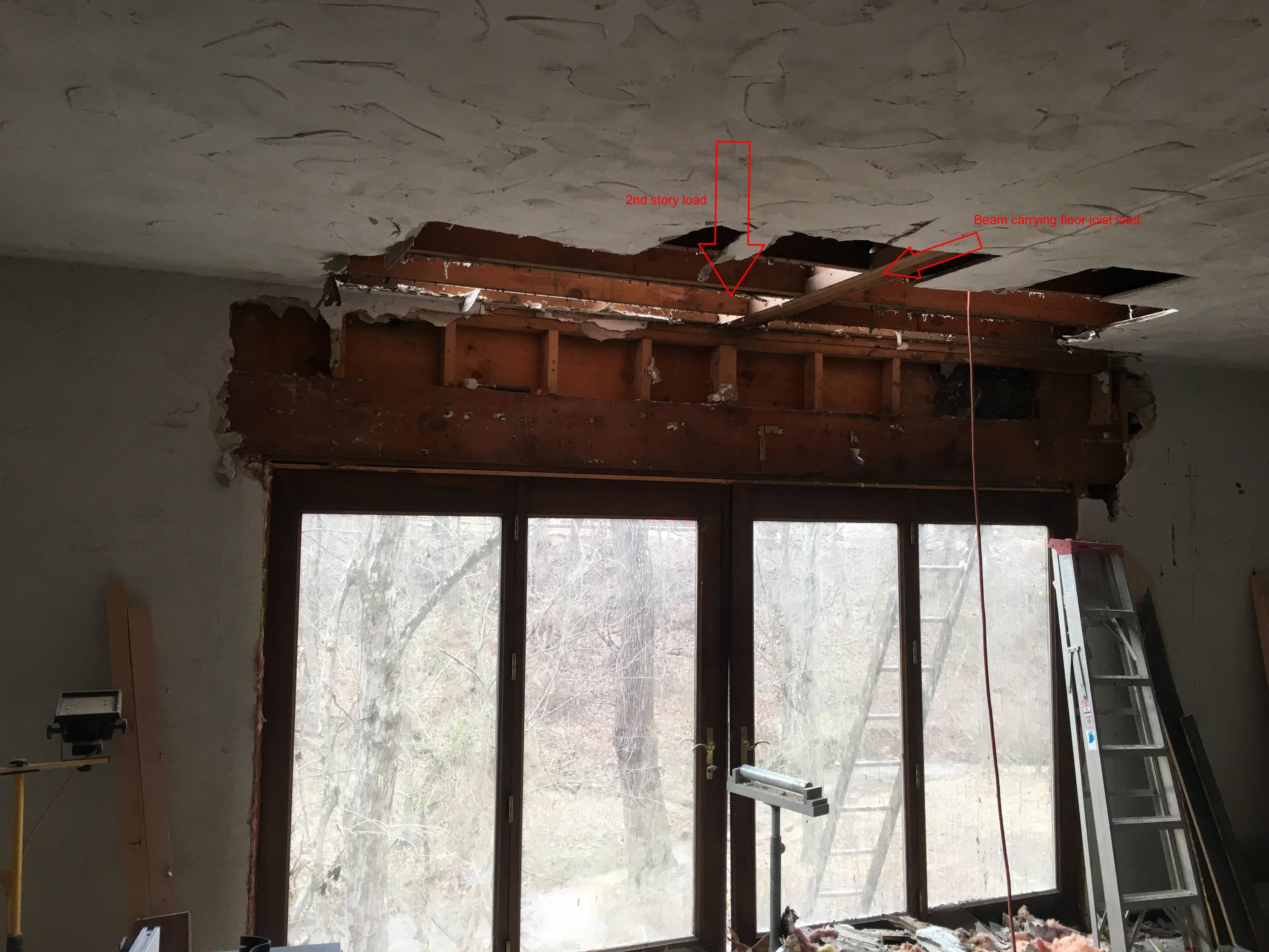
Technically there could exist a table for your transfer beam. Analogous to the new deck footing table in the 2021 IRC, such a table would require you to understand the concept of "tributary area." I couldn't find such a table.
Your transfer beam has contributions from two elevations. For the contribution from the roof elevation, the tributary area is (13ft/2)(23ft/2) = 75ft². For 10 psf dead load and 30 psf snow load, that's (40psf)(75ft²) = 3000#. Not all of this load shows up at the transfer beam, however. Moving the load from the post bases to the carrier beam, the 3000# becomes (3000#)(8ft)/(12ft) = 2000# (the remaining 1000# shows up at the exterior walls). Moving the 2000# to the transfer beam, the 2000# becomes (2000#)(147in)/(177in) = 1700# (the remaining 300# shows up at the other end of the carrier beam). For this part of the analysis, I used the sleeping room width instead of the tapered roof width. The result is conservative.
For the load from the sleeping rooms, I use 10 psf for the dead load and 30 psf for the live load. The load contribution, then, is (40psf)(23ft/2)(14.75ft/2) = 3400#.
The total midspan load is 1700# + 3400# = 5100#.
Deflection
#2 Spruce-Pine-Fir has an elastic modulus of 1,400,000 psi. The IRC prescribes a minimum deflection of L/360 = (144in)/360 = 0.4in. For 30 psf live load from the sleeping room and 20 psf live load from the roof, I get a midspan live load of (1700#)(20psf)/(40psf) + (3400#)(30psf)/(40psf) = 3400#. Two 2×12s have a deflection of
(1/48)(3400#)(144in)³/[(1400000psi)(1/12)(3.0in)(11.5in)³] = 0.40in,
just barely satisfying the deflection requirement.
Strength
Assuming that the header takes 3 or more 2×12s, I use the NDS's 1.15 repetitive use factor. #2 Spruce-Pine-Fir has an adjusted bending strength of (1.15)(875psi) = 1010psi. The strength of a single 2x12, then, is
(1010psi)(1/6)(1.5in)(11.5in)² = 33300#-in.
Given the 5100# demand from earlier, the bending demand of the transfer beam is (5100#)(144in)/4 = 184000#-in. Taking (184000#-in)/(33300#-in) = 5.5, I find that you need 6 2×12s to satisfy the demand on the transfer beam.
Supplementing the existing pair of 2×12 with deeper LVLs or higher grade 2×12s is a bit complicated. You can't just add strengths for a beam that mixes LVLs and/or different grades. The problem is that different layers in such a beam fail at different loads, where the failed layers quickly lose strength. See Figures 6.24 and 6.25 from page 149 of Computational modeling of strand-based wood composites in bending. Looking up some random LVL data, it looks like a single 1-3/4"×16" LVL has sufficient strength without any contribution from the 2×12s. Maybe you can remove the cripple studs and install such an LVL tight to the underside of the carrier beam.
Jack Studs
The jack stud configuration is predicated on the solution implemented, so it will have to wait for more details from you.
Other problems
- Much of this analysis is moot if the carrier beams and/or joists don't have the strength to deliver the loads to the transfer beams.
- I compute a demand/capacity ratio of 1.5 for the roof elevation header assuming #2 Spruce-Pine-Fir. It needs a sister.
- Since the floor joists beneath the posts from the roof elevation haven't been modified in any way, they have effectively zero capacity beyond their walking surface duties. I suspect that their demand/capacity ratio is far worse than the downstairs transfer beam.
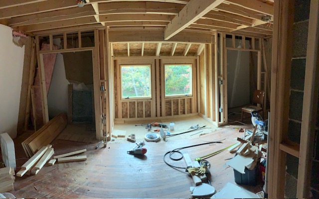
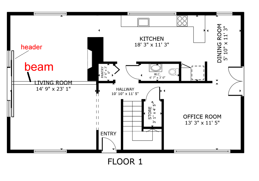
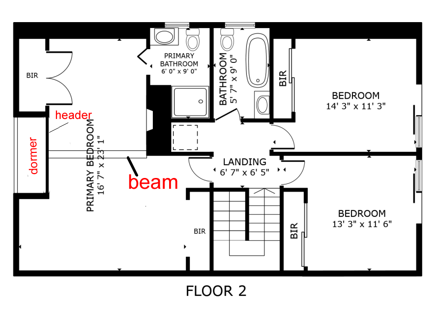
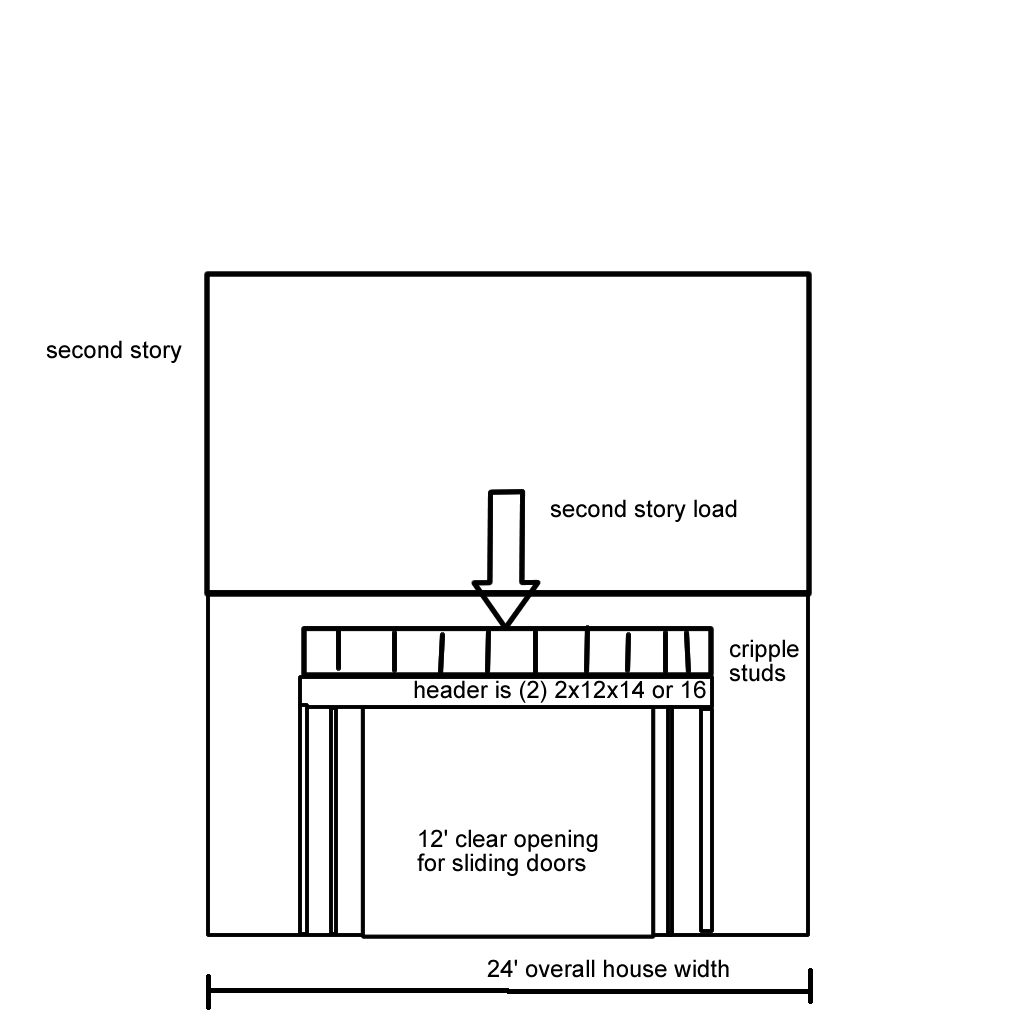
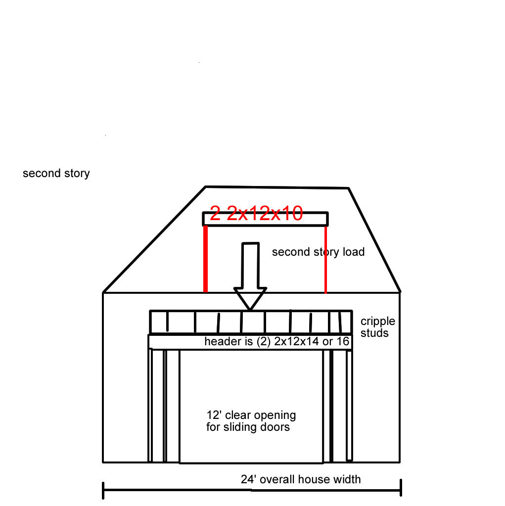 I have a house which has a footprint of roughly 40 feet long and 24 feet wide. On the side in question, one of the 24' sides, there is an existing 4 panel glass door system in place. This room has 10' ceilings. The second story load in this room is carried by (3) 2x8x12's as a beam. This beam terminates at the side of the home above the glass panels. There is a cripple stud truss (for lack of a better description) where this beam terminates and the load is carried down onto (2) 2x12x14 or 16, I don't have an exact measure of the length but its between 14' and 16'. The actual clear opening for the sliding doors is 12'. And the double 2x12x14/16 is supported on either side by several 2x4's.
