9

have another issue with another outlet in this very improperly done house I just bought. During my slow replacing of all the wall outlets, I came across this new one which has me baffled on how to translate this to a standard outlet. Here's what I'm currently looking at and the new outlet I'm trying to get this all wire to... for simplicity, I have the outlet ports numbered and the three wires with letters. I'm assuming we all know what ground is, so we can ignore that since it's pretty simple.

Diagram of outlet Wires (A) - From what I can tell, wire set A goes to another outlet or continue the feed for that line of power.

Wires (B) - This is the power coming to this box (tested with a volt meter to 120v)

Wires (C) - This set goes to a Light switch that powers lights in that same room which ends there (does not continue from that switch). This switch controlled only the lights and not the outlet.

Now, the outlet that was there was busted and never worked, so I can't be 100% certain the switch didn't also control the outlet, but I figure that would be really weird to have a switch that controls an outlet AND recessed lighting. This used to be an office before we moved in. In my haste to get this quickly changed over to a new outlet I completely forgot to document how the old busted switch had them plugged in... but here's what I do know about the old switch:

  • The middle connector piece on one side was broken, so each outlet was separate.
  • Wire set A and B were pig tailed to the bottom half of the old outlet
  • ALL other wires were push plugged into the old outlet.

So, that all being said... here's what I've tried so far to no success.

  • I tried to pigtail all the blacks together and put them into screw #3 and all the whites pigtailed into screw #1... that tripped the circuit breaker when I turned the power back on. Bad idea. Tab between the two outlets was NOT broken.
  • I tried pigtailing A and B together with blacks into screw #3 and whites into #1. Tab between outlets is NOT broken. Power to both outlets, but of course no power to the light switch.
  • I tried pigtailing A and B together with blacks into screw #4 and whites into #2. I put C black into 3 and C white into 1. Tab between outlets IS broken. Power back on... I get power to the bottom outlet but no power to the top outlet and the light switch does not power on.

What am I missing here? Thanks for the read!

7
  • 2
    Where were the wires from line C plugged into the back of the old receptacle? Is there continuity between the white and black wires in cable C when the switch is on? When the switch is on, do you get line voltage (120V) between the white and black wire of cable C?
    – Tester101
    Commented Jan 30, 2016 at 13:06
  • When you say that wire C goes to the light switch and "ends there", do you mean that it is the only thing coming into the switch box or is there another wire going from the switch box to the light?
    – Comintern
    Commented Jan 30, 2016 at 13:46
  • 3
    Crazy good image there.
    – TFK
    Commented Jan 31, 2016 at 0:32
  • @Tester101 - There's no power from the C black and white wires coming out into the wall box or going to the switch when they are not plugged into anything in the wall box. I tested both sides with the power on when C isn't plugged into anything. Commented Jan 31, 2016 at 5:51
  • @Comintern - I mean that from what I can tell without opening the wall and tracing the C wires, I believe it only goes to that wall switch and doesn't continue on to anything else (aside from the light). Commented Jan 31, 2016 at 5:52

5 Answers 5

6

First, your illustrations are Mad Awesome. You could illustrate electrical books. Literally. You might even talk to Mike Holt or others doing electrical docs.

You still have some knowledge gaps, so I'd school up some more. For a guy as smart as you, knowledge is cheap.

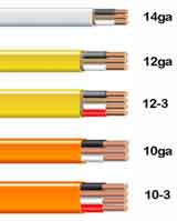
If you are good at visual, stay with that. Buy a variety-pack of electrical tape colors, and a couple feet of 12/3 cable because it's a cheap way to get a variety of wire colors for pigtails. 12 gauge is the universal donor size, it is acceptable on any common 120v circuit up to 20 amp breaker. 14ga is only allowed on 15A breakers/with 14ga wire.

enter image description here NM Romex cables

First, permanently wrap (tag) the white wire of cable C with red tape. From your comments elsewhere that there is only one cable going to the switch, that is a switch loop. Also open up the switch box and wrap the other end of that same white wire.

Next, permanently wrap (tag) the black wire of cable A with red tape. Since the switch is a switch loop, this cable is the only possible way the lights could possibly be receiving (switched) power.

Now grab your receptacle and some stripped Romex and sit at a convenient workbench. Put 6" pigtails of wire as follows. Use the screw terminals or screw-and-clamp if you have that type. Avoid backstabs (they're not reliable) and never use 12AWG on a backstab.

  • Ground terminal: a bare (or green) wire.
  • screw 1: a white wire.
  • screw 2: nothing, but if the tab between 1 and 2 has been broken, a white wire.
  • screw 3: a black wire.
  • screw 4: nothing, but if the tab between 3 and 4 is broken, a black wire.

Ready?

Splice all same colors together.

See, what I did was color-code all the wires to their function rather than the default colors of /2 cable. The switch loop has only hot (black) and switched-hot (red). The wire to the lights needs switched-hot (red) and real neutral (white).

In new work, they commonly use red for the switched hot, because the law now requires neutral in switch loops (for smart switches). So they run some /3 cable up there.

3
  • While I appreciate the initial comments on my diagram work (I've been told that before) I think you under estimate my knowledge of this. I've been replacing a lot of crazy outlets in this house with really crazy wiring & bringing them up to code. I've bought several electrical books, read online tutorials, watched youtube videos, chatted with home construction people, and I've come to this site if all else fails. I know what a pigtail is, have a really high end wire stripper, have romex, have a box with every size wirenut, and know that some of the wires in the house are 12 and some 14 gauge. Commented Jan 31, 2016 at 6:02
  • I may not use the terminology correctly (I'm a visual guy, as you can see from my diagram) but I have a pretty good idea of what I'm doing and how circuits work. 90% of the outlets in this house, so far that I've changed, I've been able to figure out... even when they are very badly done. Every now & then I hit a really head scratching one that I can't figure out how they did it; especially when they often used older outlets/switches or mickey moused them in a way I won't redo and would rather bring up to code. This is one of those crazy ones that I can't seem to figure out how it was done. Commented Jan 31, 2016 at 6:06
  • That all being said... had an aviation photoshoot today so tomorrow I'm going to try and tackle this outlet again, I'll report back with what I find. Commented Jan 31, 2016 at 6:09
1

Probably waay late, but isn't it as simple as A goes to your lighting circuit, B is your mains/feed/power, and C is your switch leg (lot of old wiring s like that). If so,

B-Black goes to 4

B-White goes to 2

C-Black goes to A Black

C-White goes to 3 (but wrap of red tape or black tape on wire)

A-Black goes to C Black

A-White goes to 1

This assumes that C is wired to a 2-screw Single Pole-Single Throw Switch and is wired with white feeding hot to Switch (wrap with red or black tape) and black returns that power when switch is closed.

Kudos on DWG, awesome graphic. Though I would lable differently Mains=A, Switch=B, Lighting=C Outlet bottom being Bottom Hot 1, Top Hot 2, Bottom Neutral 3, Top Neutral 4. Then even the lettering and numbering would make sense. :D

Maxwell

2
  • Don't worry about necromancy out here :) We support and encourage it ;) Commented Jan 8, 2018 at 3:18
  • Thank. When reviving a dead post, sometimes the sharks come for a feed. Commented Jan 9, 2018 at 5:36
0

What it sound like you may have is a 1/2 switched outlet, this is done a lot in house. You are going to need to check line C (the switch) for continuity with a meter. First turn off the breaker that controls that area. Second check the switch, with a meter or non contact voltage tester, that the power is off. Third, knowing that the power is off, turn on the switch and check continuity between the black and white wire, at your the problem outlet Box. If you get continuity then you could do the same thing as before using the black (of line C) for power and the white (of line C) as the switch leg for the top part of the receptacle.

0

It looks like cable C is not what you think it is, or is shorted between black and white somewhere. If your house had been wired by a sane electrician I would advise searching out the short in the C branch.

Of course this is just a wild guess -- but given the context it's possible that the switch on the C branch was changed to control half of the outlet. Rather than properly replacing the cable with a 3-wire as far as the light switch, Dr. Frankenstein decided to re-purpose the bare ground wire of cable C as a neutral, with either the white or black feeding back from the switch to half the outlet.

You have to open the switch box and see how it's actually wired. You are going to open this box anyway to check the continuity of the cable.

As always, be careful. Don't trust any neutrals to be neutral or any grounds to be grounded -- hot wires could be anywhere.

3
  • I actually replaced the cable C switch a while back with an older JASCO z-wave one that does not need a neutral. The wires going to the switch were your typical black, white, and ground. That was probably the easiest switch to replace in this crazy house so far! And, as of right now I have it pulled out of the wall as I've been testing everything. When cable C isn't connected to the wall outlet, the switch has no power (it has a small blue led light on the switch when it is energized so I can tell right away) Commented Jan 31, 2016 at 5:55
  • Apparently my wild guess was too wild even for your house. It's hard to give good advice without actually being right there with you -- so I'll just give advice. Commented Jan 31, 2016 at 15:33
  • You reported in your OP that when you connect power to branch C, at the outlet box, it trips the breaker. (The outlet device is just adding confusion to your description.) I would disconnect everything in branch C and test each bit in isolation for a short. Commented Jan 31, 2016 at 15:33
0

Don't know if you already got the answer here but I just changed a 3 wire socket. These were the 3wire flat wrapped type. 1)Stripped all wires, 2)hot wire for light switch on copper screw, 3) hot wire for plug #1 on second copper screw, 4)hot wire for plug #2 insert in hole on back, 5)null wire #1 on silver screw, 6)null wire #2 on second silver screw, 7)null wire #3 inserted in hole on back. Wrap one green wire around green screw. Twist together 2nd and 3rd green wire together and cap. Worked first time. No problem.

Not the answer you're looking for? Browse other questions tagged or ask your own question.