removed old text and ascii diagram
Source Link
Tony
  • 1
  • 2

enter image description hereenter image description hereI'm

I'm trying to replace a basic on/off switch for the fan in my powder room with a timer switch (which requires a neutral). The timer switch comes with red, white, black and green wirenwires.

In the same box there's also an existing light switch.

In the electrical box, the layout is (W=white wire, B=black wire)

WB       WB           |||||||           WB       WB

LL       LR           ||||||||||||          RL       RR    - my labels corresponding to above four connections

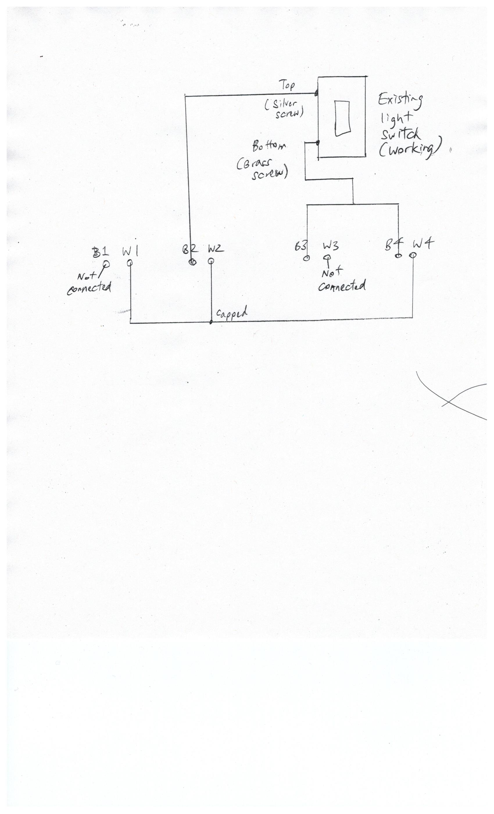
The top of the existing light switch is connected to the black wire of LR. The bottom of the existing light switch is connected to the black wire of RL and RR.

All white (neutral?) wires are connected together.

The green ground wire was connected to the electrical box. I connected the black wire of the timer to the same connection as the bottom of the existing light switch, i.e. RL and RR. I connected the red wire of the timer to black wire of LL. The white wire of the timer is connected to the neutral gang.

The fan is now on constantly and won't turn off. The blue LED light on the timer switch that indicates it's working is lit up.

If I switch the connections of the timer's black and red wires, i.e. red wire to the same connection as the bottom of the existing light switch (i.e. RL and RR), and the black wire to the black wire of LL, the fan also runs constantly and won't turn off, but the blue LED light on the timer switch however are not lit.

How should I connect these wires so the switch will work?

enter image description hereenter image description hereI'm trying to replace a basic on/off switch for the fan in my powder room with a timer switch (which requires a neutral). The timer switch comes with red, white, black and green wiren.

In the same box there's also an existing light switch.

In the electrical box, the layout is (W=white wire, B=black wire)

WB       WB           |||||||           WB       WB

LL       LR           ||||||||||||          RL       RR    - my labels corresponding to above four connections

The top of the existing light switch is connected to the black wire of LR. The bottom of the existing light switch is connected to the black wire of RL and RR.

All white (neutral?) wires are connected together.

The green ground wire was connected to the electrical box. I connected the black wire of the timer to the same connection as the bottom of the existing light switch, i.e. RL and RR. I connected the red wire of the timer to black wire of LL. The white wire of the timer is connected to the neutral gang.

The fan is now on constantly and won't turn off. The blue LED light on the timer switch that indicates it's working is lit up.

If I switch the connections of the timer's black and red wires, i.e. red wire to the same connection as the bottom of the existing light switch (i.e. RL and RR), and the black wire to the black wire of LL, the fan also runs constantly and won't turn off, but the blue LED light on the timer switch however are not lit.

How should I connect these wires so the switch will work?
enter image description hereenter image description here

I'm trying to replace a basic on/off switch for the fan in my powder room with a timer switch (which requires a neutral). The timer switch comes with red, white, black and green wires.

In the same box there's also an existing light switch.

Added wiring diagram (B= black, W= white). If I connect W3 to the rest of the capped white wires, then the fan runs constantly even when B1 is not connected.
Source Link
Tony
  • 1
  • 2

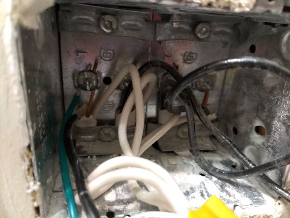
enter image description hereenter image description hereI'm trying to replace a basic on/off switch for the fan in my powder room with a timer switch (which requires a neutral). The timer switch comes with red, white, black and green wiren.

In the same box there's also an existing light switch.

In the electrical box, the layout is (W=white wire, B=black wire)

WB       WB           |||||||           WB       WB

LL       LR           ||||||||||||          RL       RR    - my labels corresponding to above four connections

The top of the existing light switch is connected to the black wire of LR. The bottom of the existing light switch is connected to the black wire of RL and RR.

All white (neutral?) wires are connected together.

The green ground wire was connected to the electrical box. I connected the black wire of the timer to the same connection as the bottom of the existing light switch, i.e. RL and RR. I connected the red wire of the timer to black wire of LL. The white wire of the timer is connected to the neutral gang.

The fan is now on constantly and won't turn off. The blue LED light on the timer switch that indicates it's working is lit up.

If I switch the connections of the timer's black and red wires, i.e. red wire to the same connection as the bottom of the existing light switch (i.e. RL and RR), and the black wire to the black wire of LL, the fan also runs constantly and won't turn off, but the blue LED light on the timer switch however are not lit.

How should I connect these wires so the switch will work?
enter image description hereI'm trying to replace a basic on/off switch for the fan in my powder room with a timer switch (which requires a neutral). The timer switch comes with red, white, black and green wiren.

In the same box there's also an existing light switch.

In the electrical box, the layout is (W=white wire, B=black wire)

WB       WB           |||||||           WB       WB

LL       LR           ||||||||||||          RL       RR    - my labels corresponding to above four connections

The top of the existing light switch is connected to the black wire of LR. The bottom of the existing light switch is connected to the black wire of RL and RR.

All white (neutral?) wires are connected together.

The green ground wire was connected to the electrical box. I connected the black wire of the timer to the same connection as the bottom of the existing light switch, i.e. RL and RR. I connected the red wire of the timer to black wire of LL. The white wire of the timer is connected to the neutral gang.

The fan is now on constantly and won't turn off. The blue LED light on the timer switch that indicates it's working is lit up.

If I switch the connections of the timer's black and red wires, i.e. red wire to the same connection as the bottom of the existing light switch (i.e. RL and RR), and the black wire to the black wire of LL, the fan also runs constantly and won't turn off, but the blue LED light on the timer switch however are not lit.

How should I connect these wires so the switch will work?

enter image description hereenter image description hereI'm trying to replace a basic on/off switch for the fan in my powder room with a timer switch (which requires a neutral). The timer switch comes with red, white, black and green wiren.

In the same box there's also an existing light switch.

In the electrical box, the layout is (W=white wire, B=black wire)

WB       WB           |||||||           WB       WB

LL       LR           ||||||||||||          RL       RR    - my labels corresponding to above four connections

The top of the existing light switch is connected to the black wire of LR. The bottom of the existing light switch is connected to the black wire of RL and RR.

All white (neutral?) wires are connected together.

The green ground wire was connected to the electrical box. I connected the black wire of the timer to the same connection as the bottom of the existing light switch, i.e. RL and RR. I connected the red wire of the timer to black wire of LL. The white wire of the timer is connected to the neutral gang.

The fan is now on constantly and won't turn off. The blue LED light on the timer switch that indicates it's working is lit up.

If I switch the connections of the timer's black and red wires, i.e. red wire to the same connection as the bottom of the existing light switch (i.e. RL and RR), and the black wire to the black wire of LL, the fan also runs constantly and won't turn off, but the blue LED light on the timer switch however are not lit.

How should I connect these wires so the switch will work?

added 12 characters in body
Source Link
isherwood
  • 149k
  • 8
  • 179
  • 439

enter image description hereI'm trying to replace a basic on/off switch for the fan in my powder room with a timer switch (which requires a neutral). The timer switch comes with red, white, black and green wiren.

In the same box there's also an existing light switch.

In the electrical box, the layout is (W=white wire, B=black wire)

WB WB ||||||| WB WB

LL LR |||||||||||| RL RR - my labels corresponding to above four connections

WB       WB           |||||||           WB       WB

LL       LR           ||||||||||||          RL       RR    - my labels corresponding to above four connections

The top of the existing light switch is connected to the black wire of LR. The bottom of the existing light switch is connected to the black wire of RL and RR.

All white (neutral?) wires are connected together.

The green ground wire was connected to the electrical box. I connected the black wire of the timer to the same connection as the bottom of the existing light switch, i.e. RL and RR. I connected the red wire of the timer to black wire of LL. The white wire of the timer is connected to the neutral gang.

The fan is now on constantly and won't turn off. The blue LED light on the timer switch that indicates it's working is lit up.

If I switch the connections of the timer's black and red wires, i.e. red wire to the same connection as the bottom of the existing light switch (i.e. RL and RR), and the black wire to the black wire of LL, the fan also runs constantly and won't turn off, but the blue LED light on the timer switch however are not lit.

How should I connect these wires so the switch will work?

enter image description hereI'm trying to replace a basic on/off switch for the fan in my powder room with a timer switch (which requires a neutral). The timer switch comes with red, white, black and green wiren.

In the same box there's also an existing light switch.

In the electrical box, the layout is (W=white wire, B=black wire)

WB WB ||||||| WB WB

LL LR |||||||||||| RL RR - my labels corresponding to above four connections

The top of the existing light switch is connected to the black wire of LR. The bottom of the existing light switch is connected to the black wire of RL and RR.

All white (neutral?) wires are connected together.

The green ground wire was connected to the electrical box. I connected the black wire of the timer to the same connection as the bottom of the existing light switch, i.e. RL and RR. I connected the red wire of the timer to black wire of LL. The white wire of the timer is connected to the neutral gang.

The fan is now on constantly and won't turn off. The blue LED light on the timer switch that indicates it's working is lit up.

If I switch the connections of the timer's black and red wires, i.e. red wire to the same connection as the bottom of the existing light switch (i.e. RL and RR), and the black wire to the black wire of LL, the fan also runs constantly and won't turn off, but the blue LED light on the timer switch however are not lit.

How should I connect these wires so the switch will work?

enter image description hereI'm trying to replace a basic on/off switch for the fan in my powder room with a timer switch (which requires a neutral). The timer switch comes with red, white, black and green wiren.

In the same box there's also an existing light switch.

In the electrical box, the layout is (W=white wire, B=black wire)

WB       WB           |||||||           WB       WB

LL       LR           ||||||||||||          RL       RR    - my labels corresponding to above four connections

The top of the existing light switch is connected to the black wire of LR. The bottom of the existing light switch is connected to the black wire of RL and RR.

All white (neutral?) wires are connected together.

The green ground wire was connected to the electrical box. I connected the black wire of the timer to the same connection as the bottom of the existing light switch, i.e. RL and RR. I connected the red wire of the timer to black wire of LL. The white wire of the timer is connected to the neutral gang.

The fan is now on constantly and won't turn off. The blue LED light on the timer switch that indicates it's working is lit up.

If I switch the connections of the timer's black and red wires, i.e. red wire to the same connection as the bottom of the existing light switch (i.e. RL and RR), and the black wire to the black wire of LL, the fan also runs constantly and won't turn off, but the blue LED light on the timer switch however are not lit.

How should I connect these wires so the switch will work?

Added picture
Source Link
Tony
  • 1
  • 2
Loading
Source Link
Tony
  • 1
  • 2
Loading