added 3 characters in body; edited title
Source Link
Solar Mike
  • 28.7k
  • 2
  • 33
  • 66

Why isare there 3 wire conductors on this outlet circuit

Hey there imI’m an apprentice electrician and still learning so please forgive me on my lack of knowledge here, but iI had a friend who asked me to change out some receptacles in theretheir house for them which sounded like a straightforward task that I've done before, but the issue iI ran into is something iI haven't seen and experienced yet. There

There are 3 wire conductors feeding 3 outlets on this circuit (Red, Black, White and bare copper) and I've never seen a third wire (Red) for outlets before, and unfortunately my friend had removed them all already to do some painting so iI was not able to see for myself how they were wired before, so iI checked for voltaged where the power comes into the first box to see which wires where hot and iI was getting 120v on the Red and 20v on the Black, at this point iI asked my friend how the old ones where wired up and iI installed the new ones accordingly as shown in my picture diagram (sorry for my poor MS paint abilities) and iI powered them up and checked them with my receptacle tester and it said it was wired correctly and worked.

So i'mI'm wondering is this actually correct?

If this is not correct how should it be wired?

And why is there a 3rd wire?

Also is the 20v iI got on the black wire just phantom voltage?

IdI’d greatly appreciate the help and knowledge!

enter image description here

Why is there 3 wire conductors on this outlet circuit

Hey there im an apprentice electrician and still learning so please forgive me on my lack of knowledge here, but i had a friend who asked me to change out some receptacles in there house for them which sounded like a straightforward task that I've done before, but the issue i ran into is something i haven't seen and experienced yet. There are 3 wire conductors feeding 3 outlets on this circuit (Red, Black, White and bare copper) and I've never seen a third wire (Red) for outlets before, and unfortunately my friend had removed them all already to do some painting so i was not able to see for myself how they were wired before, so i checked for voltaged where the power comes into the first box to see which wires where hot and i was getting 120v on the Red and 20v on the Black, at this point i asked my friend how the old ones where wired up and i installed the new ones accordingly as shown in my picture diagram (sorry for my poor MS paint abilities) and i powered them up and checked them with my receptacle tester and it said it was wired correctly and worked.

So i'm wondering is this actually correct?

If this is not correct how should it be wired?

And why is there a 3rd wire?

Also is the 20v i got on the black wire just phantom voltage?

Id greatly appreciate the help and knowledge!
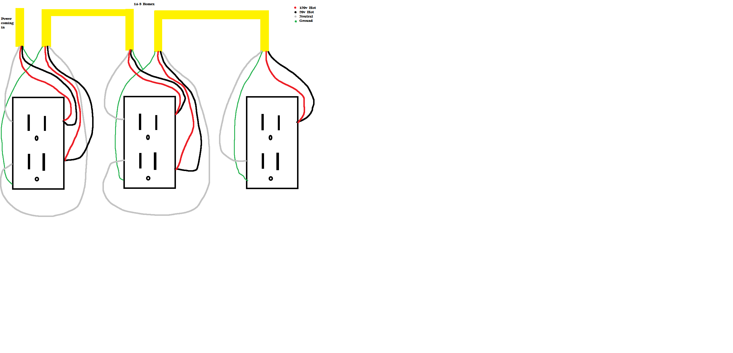
enter image description here

Why are there 3 wire conductors on this outlet circuit

Hey there I’m an apprentice electrician and still learning so please forgive me on my lack of knowledge here, but I had a friend who asked me to change out some receptacles in their house for them which sounded like a straightforward task that I've done before, but the issue I ran into is something I haven't seen and experienced yet.

There are 3 wire conductors feeding 3 outlets on this circuit (Red, Black, White and bare copper) and I've never seen a third wire (Red) for outlets before, and unfortunately my friend had removed them all already to do some painting so I was not able to see for myself how they were wired before, so I checked for voltaged where the power comes into the first box to see which wires where hot and I was getting 120v on the Red and 20v on the Black, at this point I asked my friend how the old ones where wired up and I installed the new ones accordingly as shown in my picture diagram (sorry for my poor MS paint abilities) and I powered them up and checked them with my receptacle tester and it said it was wired correctly and worked.

So I'm wondering is this actually correct?

If this is not correct how should it be wired?

And why is there a 3rd wire?

Also is the 20v I got on the black wire just phantom voltage?

I’d greatly appreciate the help and knowledge!

enter image description here

Source Link

Why is there 3 wire conductors on this outlet circuit

Hey there im an apprentice electrician and still learning so please forgive me on my lack of knowledge here, but i had a friend who asked me to change out some receptacles in there house for them which sounded like a straightforward task that I've done before, but the issue i ran into is something i haven't seen and experienced yet. There are 3 wire conductors feeding 3 outlets on this circuit (Red, Black, White and bare copper) and I've never seen a third wire (Red) for outlets before, and unfortunately my friend had removed them all already to do some painting so i was not able to see for myself how they were wired before, so i checked for voltaged where the power comes into the first box to see which wires where hot and i was getting 120v on the Red and 20v on the Black, at this point i asked my friend how the old ones where wired up and i installed the new ones accordingly as shown in my picture diagram (sorry for my poor MS paint abilities) and i powered them up and checked them with my receptacle tester and it said it was wired correctly and worked.

So i'm wondering is this actually correct?

If this is not correct how should it be wired?

And why is there a 3rd wire?

Also is the 20v i got on the black wire just phantom voltage?

Id greatly appreciate the help and knowledge!

enter image description here